Bin Picking Tutorial: Setting up Photoneo Bin Picking Studio with KUKA robots
NOTE: Users are strongly recommended to read the general introduction to robot interfaces prior to installing specific robot modules.
Contents
1. Prerequisities
Photoneo KUKA module prerequisities:
- - KRC4 system v.8.3 or higher
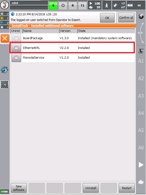
- - Ethernet KRL Interface v.2.2.8 installed
In order to check if Ethernet KRL is available on the robot controller, switch to Expert Mode and browse to Menu -> Startup -> Additional Software:
2. KUKA Controller setup
The following tutorial gives a step by step guide of how to configure your KUKA KRC4 controller and install all the necessary files you will need to get the robot interface for Photoneo Binpicking Studio up and running.
This tutorial was originally written using the latest KRC4 system version 8.3 and KUKA AGILUS KR6 R900 sixx robot.
2.1 Network configuration
Photoneo KUKA Module utilizes TCP/IP communication for transferring data between KRC4 Robot Controller and Bin Picking Studio.
As a first step in commissioning, ensure that the IP address of the KRC4 controller meets your network configuration requirements
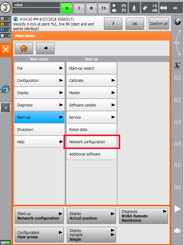
Switch to Expert Mode, open the Menu screen and select the Startup-> Network Configuration option:
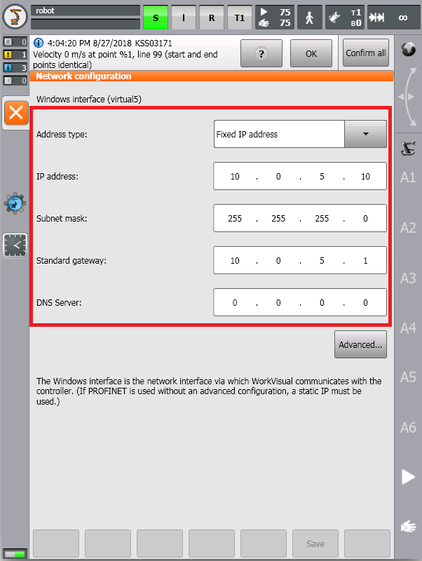
Amend the network configuration to meet your requirements:
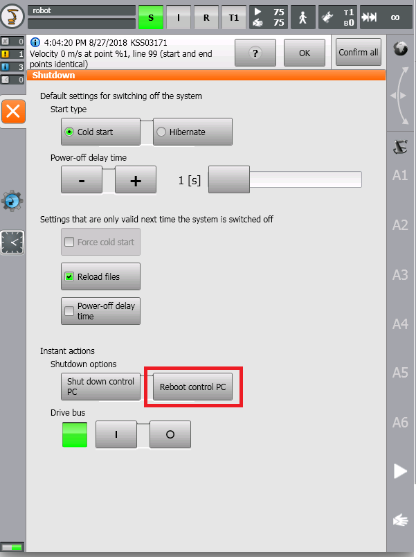
KRC4 Control PC needs to be rebooted in order to apply the new network configuration.
Open the Menu Screen and select the Shutdown -> Reboot control PC option:
3. Photoneo KUKA Module Setup
The first step in the installation of Photoneo KUKA Module is to copy the files from the Photoneo KUKA Module Archive to the Robot Controller.
The Photoneo KUKA Module consists of the following files:
- Photoneo EthernetKRL Config Folder
- - pho_bp_client.xml
- - pho_state_server.xml
- Photoneo Folder
- - pho_state_server.src
- - pho_common.src
- - pho_motion.src
- - pho_common.dat
- - pho_motion.dat
- Program Folder
- - customer_definitions.src
- - main_application.src
- - main_application.dat
3.1 Ethernet KRL config
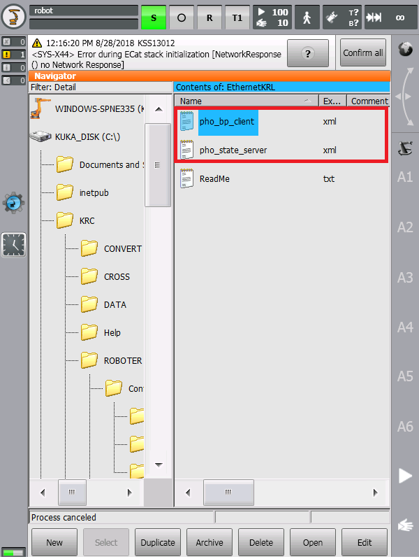
EthernetKRL Config folder contains two XML files - pho_bp_client.xml and pho_state_server.xml.
Copy these files from the USB stick to C:\KRC\Roboter\Config\User\Common\EthernetKRL\ as is shown in the figure below:
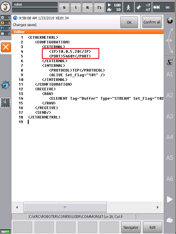
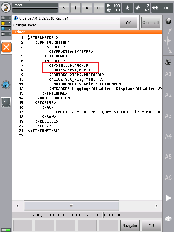
XML files contain the configuration of EKI communication interface. The only entries that need to be changed are the IP address tags.
Enter the IP address of the Vision Controller to External IP tag in pho_bp_client.xml as is shown in the figure below:
NOTE: Default Bin Picking Client Port Configuration is 54601 - do not edit this tag unless approved by Photoneo Support !!!
Enter the IP address of the KUKA Robot Controller to Internal IP tag in pho_state_server.xml as is shown in the figure below:
NOTE: Default State Server Port Configuration is 54602 - do not edit this tag unless approved by Photoneo Support !!!
Save the changes and reboot the control PC again to apply the new EthernetKRL interface configuration.
Ports utilized by Photoneo KUKA Module:
- - Bin Picking Client Port: 54601
- - State Server Port: 54602
Flags occupied by EthernetKRL functions:
- - $FLAG[100] - State Server Connection Alive
- - $FLAG[101] - Bin Picking Connection Alive
- - $FLAG[102] - Bin Picking Data Received
NOTE: Do NOT use these flags and ports in the rest of your application!!!
3.2 Copy Photoneo KUKA Module files
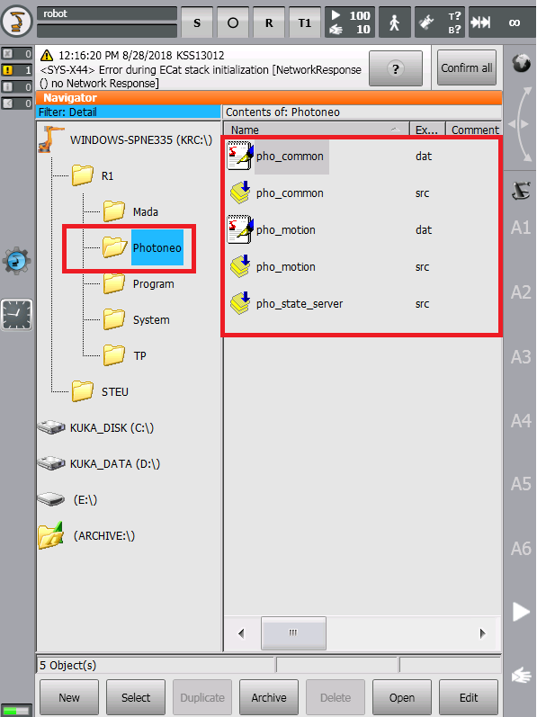
The Photoneo folder contains internal files that should not be edited by the user.
Copy the entire content of Photoneo folder from the USB Stick to the R1/Photoneo// (Compilation errors can be ignored for now - just copy the files):
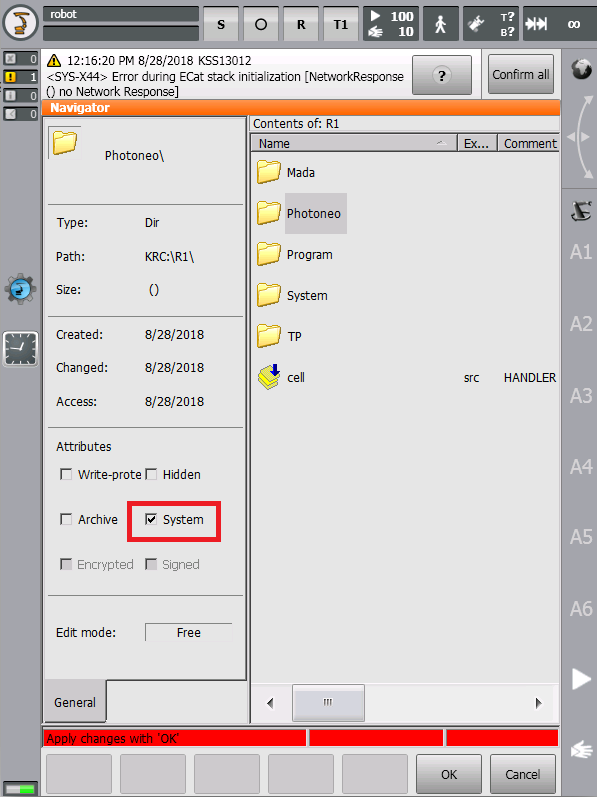
It is highly recommended to hide the Photoneo folder from the Operator's reach.
Switch to Expert Mode, and set the System flag in the Properties of the Photoneo folder:
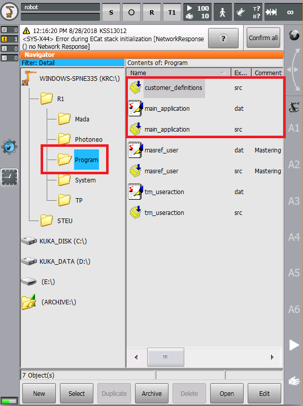
The program folder contains files which should be amended by the user in order to meet application requirements.
Do not replace the whole program folder, only copy three files from the Photono_KUKA_Module archive to R1/Program Folder:
NOTE: Compilation errors should disappear after copying all files to the robot controller.
3.3 State Server configuration
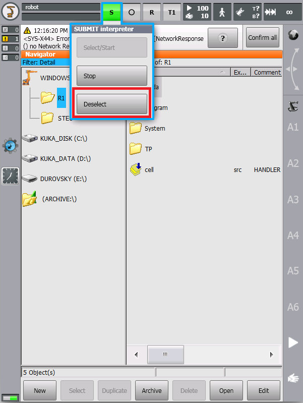
In order to get State Server up and running, it is necessary to edit the Submit Interpreter program sps.sub in R1/System.
Switch to Expert Mode and deselect the Submit Interpreter program before making any changes:
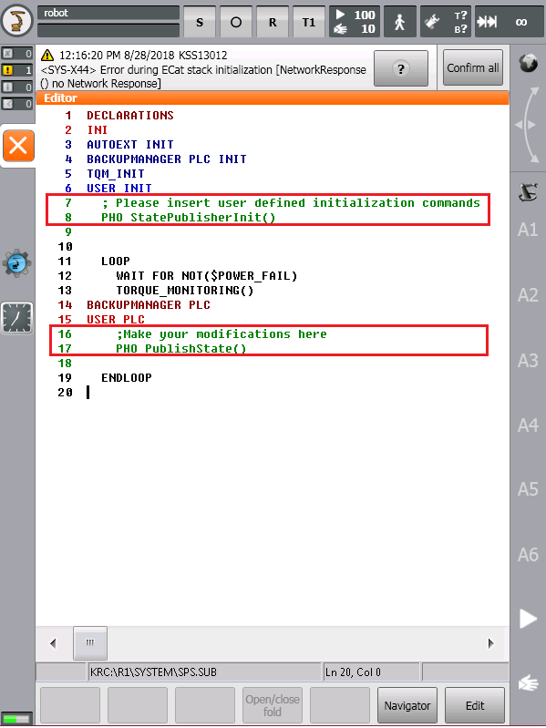
As is shown in the figure below, add the following two lines of code to the original sps.sub file.
PHO_StatePublisherInit() goes to the USER INI section while PHO_PublishState() goes to the USER PLC section:
State Server is necessary for calibration and visualization purposes. As soon as you restart Submit Interpreter, it should be up and waiting for the connection from the Bin Picking Studio.
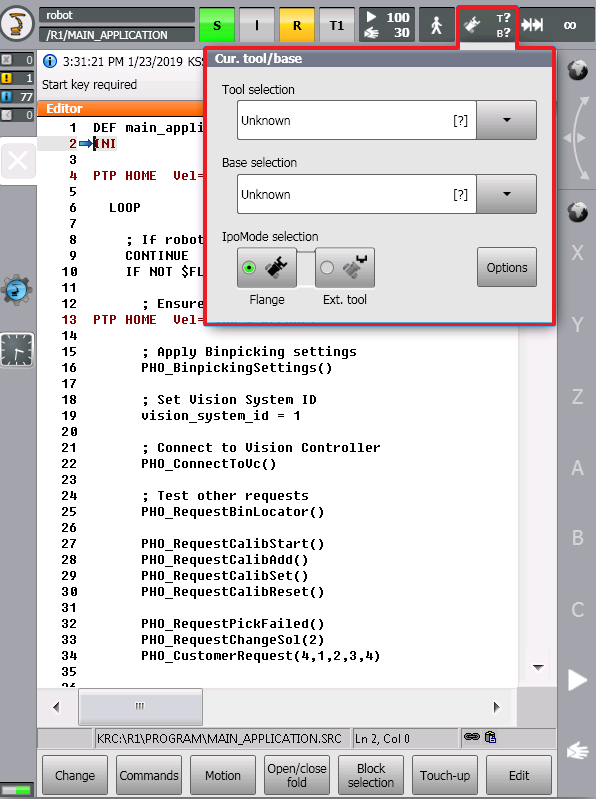
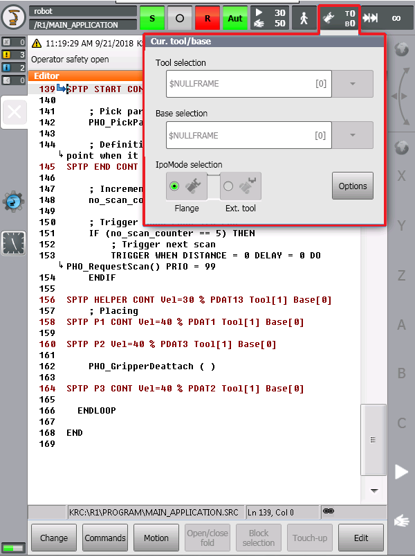
Ensure that TOOL and BASE are selected before starting calibration process. If TOOL and BASE are not selected - (T? and B?) as shown in the figure below, state server will not be able to report correct TCP to the Bin Picking Studio.
Select $NULLFRAME for both TOOL and BASE frames in order to enable proper functionality of State Server.
As was mentioned above, State Server occupies $FLAG[100] and listens on port 54601.
3.4 Bin Picking Client Configuration
The Bin Picking Client can be launched using main_application.src. The main application contains the definitions of fixed robot poses, bin picking initialization and the main bin picking loop.
3.4.1 Reteach positions
Users are expected to reteach home, start, end & placing positions before selecting this file for launch.
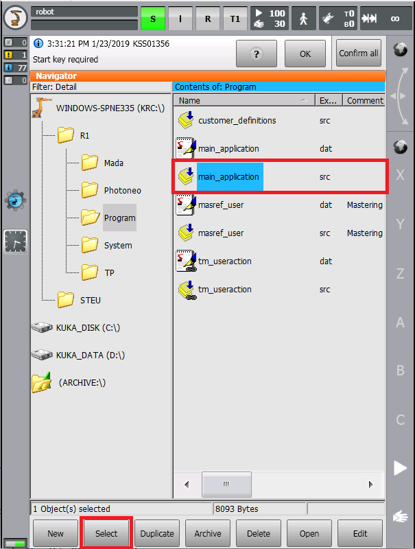
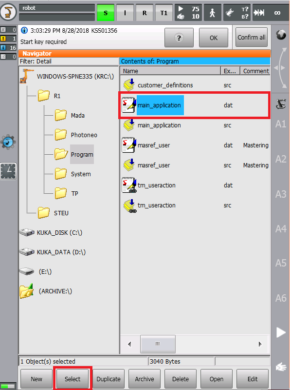
Switch to Expert Mode and Select main_application.src:
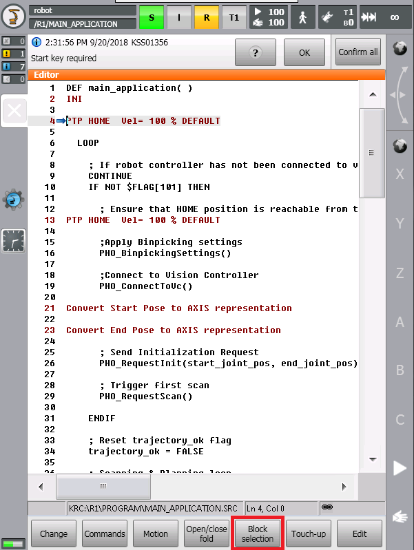
Select the program line containing pose which you are about to reteach, HOME is shown in this example:
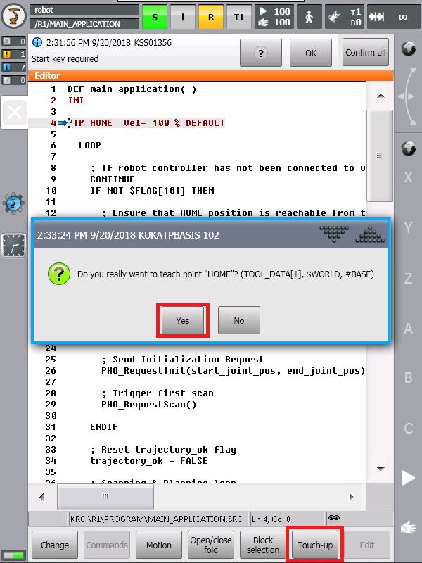
Press Block Selection button to move program pointer to the current line. Jog robot to the new pose and select Touch Up Button to reteach position:
Select Yes to confirm new position. Repeat the same procedure also for START, END and placing positions (P1, P2, P3 are used in basic template).
START and END poses are defined in the program picking section (Not at the beginning of the program as usual at other vendors).
NOTE: Ensure that HOME pose is reachable from last placing pose (P3 in the basic template) without collision. The robot might move to HOME pose directly when an error occurs!!!
3.4.1 Ports and Flags used
As was mentioned above, the Bin Picking Client occupies $FLAG[101] & FLAG[102] and utilizes Port 54602 to connect to the bin picking server running on the Bin Picking Studio.
NOTE: When PLC is used as a high-level controller, the code from main_applications.src can be divided into separate programs and launched directly from cell.src.
4. KRL
Photoneo KUKA interface was designed to be easily integrated into existing applications written in KRL code. KRL API and KRL Config should be used to adapt default bin picking template to the requirements of specific applications.
- KRL API - is set of KRL procedures used to control the bin picking sequence. Bin Picking initialization, main loop, and error handling are implemented here. Please retain the order of request calls as defined in basic template.
- KRL CONFIG - customer_definitions.src enables users to configure application specific settings such as gripper commands, velocity, acceleration and approximation distances.
4.1 KRL API
The following API describes the functionality of requests provided by the Photoneo KUKA Interface. These requests are intended for high-level control of bin picking sequences and are usually called in main_application.src
PHO_ConnectToVC() - function to establish a connection to the Bin Picking Studio. Blocking function; suspends the program until a proper connection is established.
PHO_RequestInit(start_pose:IN, end_pose:IN) - request to initialize the bin picking application on the Bin Picking Studio side. Start and End poses defined by the operator on the pendant are transferred to the Bin Picking Studio and used in the trajectory planning pipeline as start and terminus points.
PHO_RequestScan() - request to trigger the next scan and localization. Non-blocking request; the KRL program continues immediately at the next line.
PHO_WaitForScan() - function to wait for scan to be finished. This should be called after triggering the scan, but not immediately. Blocking request; the KRL program waits for the response from Bin Picking Studio.
PHO_RequestTrajectory() - request to start trajectory planning for current goal. Non-blocking function; the KRL program continues immediately at the next line.
PHO_ReceiveTrajectory() - function to receive requested bin picking operations (consisting of a sequence of trajectories and gripper commands). Blocking function; waits for bin picking data to be received.
PHO_PickObject() - request to execute bin picking operation and execute motion. Always make sure that the robot is in Start pose before invoking this function.
PHO_RequestChangeSol(solution_id:IN) - request to change currently deployed solution. Input Parameter: Solution ID
PHO_RequestCalibStart() - request to start current calibration for selected vision system and remove all previously added points (Not supported in this version)
PHO_RequestCalibAdd() - request to add calibration point - a scan is triggered and the calibration is recalculated. (Not supported in this version)
PHO_RequestCalibSet() - request to save current calibration result to selected Vision System (Not supported in this version)
PHO_RequestCalibReset() - request to reset current calibration and remove all previously added points (Not supported in this version)
PHO_RequestBinLocator() - request to localize bin position in the environment (Reserved for future use)
PHO_RequestPickFailed() - request to notify bin picking studio that object picking has failed (Reserved for future use)
NOTE #1: The PHO_ConnectToVC function should always be called as a first of Photoneo Bin Picking API procedures. It should always be followed by PHO_RequestInit function. Not obeying these order will result in a communication error.
NOTE #2: The PHO_WaitForScan has to be called after the PHO_RequestScan. A user can perform standard robotic commands between these two calls but cannot perform any other Photoneo Bin Picking API calls. The PHO_WaitForScan function has to be finished first. For example - PHO_RequestScan followed by PHO_RequestTrajectory results in communication error.
NOTE #3: The PHO_ReceiveTrajectory has to be called after the PHO_RequestTrajectory. A user can perform standard robotic commands between these two calls but cannot perform any other Photoneo Bin Picking API calls. The PHO_Receivetrajectory function has to be finished first. For example - the PHO_RequestTrajectory followed by the PHO_RequestScan results in communication error.
4.2 KRL CONFIG
customer_definitions.src enables the user to configure several bin picking settings, including gripper command implementations, trajectory speed and approximation adjustments.
- PHO_GripperAttach() - implement function for attachning object to gripper
- PHO_GripperDetach() - implement function for detachning object from gripper
- PHO_GripperUser_1() - implement custom user gripper command (reserved for future use)
- PHO_GripperUser_2() - implement custom user gripper command (reserved for future use)
- PHO_GripperUser_3() - implement custom user gripper command (reserved for future use)
- PHO_GripperUser_4() - implement custom user gripper command (reserved for future use)
- PHO_GripperUser_5() - implement custom user gripper command (reserved for future use)
- PHO_GripperUser_6() - implement custom user gripper command (reserved for future use)
- PHO_GripperUser_7() - implement custom user gripper command (reserved for future use)
- PHO_GripperUser_8() - implement custom user gripper command (reserved for future use)
- PHO_BinpickingSettings() - specify velocities, accelerations and approximation distances for bin picking trajectories (SPLINE segments). Amend the number of trajectories to meet your Bin Picking Studio Setup. (by default 4 trajectories are used)
4.3 KRL ERROR HANDLING
Photoneo KUKA interface provides basic error handling. If an error occurs during bin picking operations, the error_code global_variable contains the code of the specific error which will helps to identify the source of the problem.
PHO_NO_ERR := 0 - Service response from Bin Picking Studio is valid
PHO_SERVICE_ERR := 1 - Service response from Bin Picking Studio is invalid.
PHO_UNKNOWN_REQ := 2 - Bin Picking Studio received an unknown request.
PHO_COM_FAILURE := 3 - Communication failure due to socket closure.
PHO_BAD_DATA := 4 - Data validation check has failed.
PHO_TIMEOUT := 5 - Communication failure due to socket timeout.
PHO_LONG_TRAJ := 6 - The length of one of the trajectory segments was higher than the maximum allowed trajectory size (usually max = 100 waypoints)
PHO_UNKNOWN_ERR := 99 - Unspecified internal error
PHO_PLANNING_FAILED := 201 - Trajectory planning has failed
PHO_NO_PART_FOUND := 202 - No part has been localized
PHO_NOT_INITIALIZED := 203 - Bin picking application has not been properly initialized on Bin Picking Studio side.
PHO_PART_LOST := 204 - Part has been lost during motion execution
PHO_WRONG_BP_CONFIG := 255 - Wrong Bin Picking Configuration - Check Log Console in the Bin Picking Studio
4.4 MAIN MODULE
The following section provides the source code of main_application.src - the basic template which demonstrates how the user's application and Photoneo Bin Picking API can be integrated together.
5. Runtime
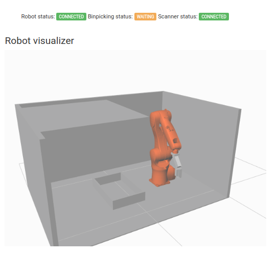
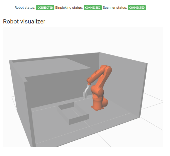
Make sure that your solution on the Deployment page of Bin Picking Studio is running and Binpicking Status is in Waiting for a connection state as is shown in the figure below:
Choose if you want to run the application in T1, T2 or AUT mode and adopt the speed override if required
Select the main_application.src from the R1/Program/ folder:
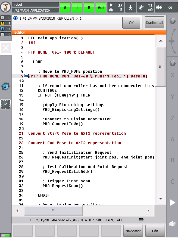
Start the program on the robot controller and you should see the program pointer start to execute the program lines:
You should also notice that Binpicking Status has changed to the Connected state. This means that the Bin Picking Studio has established a successful connection to the robot controller:
The robot should now start sending requests to the Bin Picking Studio and execute bin picking movements.
NOTE: Ensure that you are ready to halt motion execution immediately in case of any problem. It is strongly recommended to reduce the speed to 10% of maximum or less during initial bin picking tests.
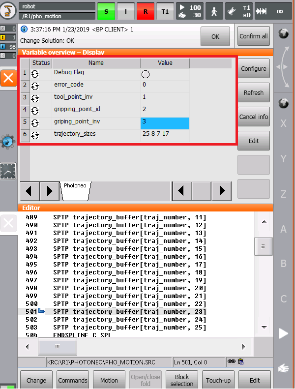
Since KUKA UI does not provide a standard "Terminal" utility, users are recommended to use Display tool to monitor values of specific bin picking related variables.
The following figure demonstrates a simple watch of basic bin picking related variables:
- - PHO_DEBUG - flag which enables user to turn msgNotify logs ON and OFF
- - error_code - if error occurs, the error code from the list above is saved to this variable.
- - tool_point_inv - contains information about Tool Point Invariance, that was used for the current pick (utilized for oriented placing)
- - gripping_point_id - contains information about Gripping Point ID that was used for the current pick (utilized for oriented placing)
- - gripping_point_inv - contains information about Gripping Point Invariance that was used for the current pick (utilized for oriented placing)
- - trajectory_sizes[] - array which contains information about the number of way-points in each segment of bin picking trajectory (By default 4 trajectory segments are used).
