3D Localization Configurator
3D Localization Configurator is a standalone application used to generate configuration file for Photoneo 3D Localization SDK. The configuration file contains the CAD of the searched object, defined gripping point and the localization parameters.
Localization Configurator requires PhoXi Control Application to connect to 3D scanner or file camera.
Contents
Overview
To download Localization SDK, visit our product webpage: Localization SDK
The Localization Configurator is installed together with the SDK. It serves as a simple wizard to generate PLCF file, which is used as an input for Localization SDK. The example code of how to use the SDK is located in installation folder, which is usually
- C:\Program Files\PhotoneoSDK\Localization\Examples\ in Windows
- \opt\PhotoneoSDK\Localization\Examples\ in Ubuntu
Copy the example directory outside the Program Files directory (because of the user rights) and use CMake to generate the project.
Setting the gripping point
The gripping point defines the point where the object should be picked by the gripper. Every gripper has a defined tool point. Gripping point and tool point together define the mutual position of the gripper and gripped object for bin picking applications.
In Localization Configurator, the gripping point has a position and orientation with respect to CAD model coordinate system. When the localization process finds the object, it returns the position and orientation of this gripping point (usually in robot coordinate space).
Localization parameters
- Overlap with model
- This percentage express how many points have to be seen on the object to consider the result correct
- Higher percentage leads to higher accuracy and longer computation time
- Amount of time
- If checked, the localization process stops after the defined time limit
- This constrain can be combined with "Number of instances"
- Number of instances
- If checked, the localization process stops after the defined number of objects is found
- This constrain can be combined with "Amount of time"
- Use Smart Memory
- If checked, the localization process remembers the positions of found objects from the last run and uses this information in new search
- This setting can strikingly speed up the localization process
- The assumption for using this setting is that the scene is mostly static (only few parts change their position between consecutive searches)
- Check occlusions only in a distance to Gripping Point
- If checked, the calculation of the object occlusion is limited only to the area in the defined distance to the gripping point
- By default (this option is not checked), object is considered occluded when there is another object on top of it (from the camera perspective)
- The assumption for using this setting is that the object can be safely picked also when there are other objects on top of it (e.g. these objects will fall down without damage when the underlying object is being picked)
Using a PRAW file in the 3D Localization Configurator
First, open the PRAW file in PhoXiControl either by dragging and dropping the PRAW file into the PhoXiControl window or by directly opening the PRAW file with PhoXiControl.
After this has been done, the Localization Configurator will have the option of using the File Camera of the PRAW file as the source scene in the localization.

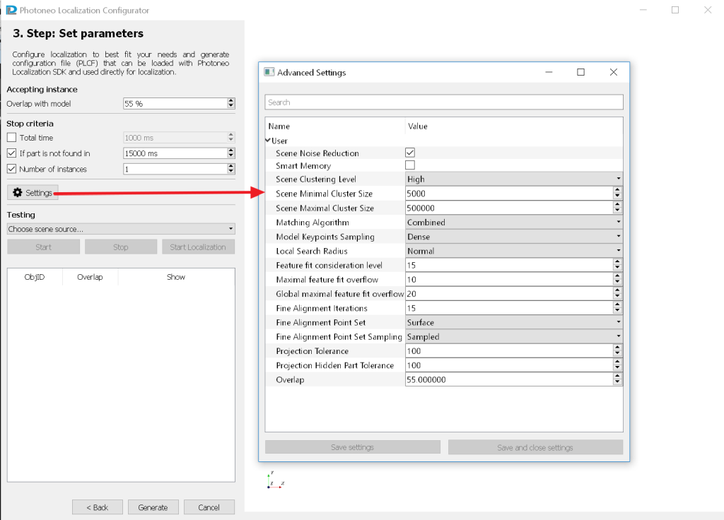
Advanced parameters
Segmentation
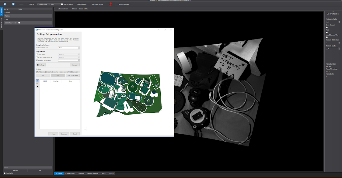
First the algorithm splits the scene into segments. Segment should be a continuous meaningful area in the scan. In the visualizer each segment has different shade of green color. When there are multiple objects in the scene, each object should have different shade of green. It does not matter when the object is split into several segments. There are 3 advanced parameters affecting the segmentation.
- Scene clustering level
higher scene clustering level increases the amount of created segments
- Scene minimal cluster size
The nominal number of points in a segment. Smaller segments are filtered out (gray color).
- Scene maximal cluster size
The nominal number of points in a segment. Bigger segments are filtered out (gray color).
Matching algorithm
The matching algorithm advanced parameter has 3 possible settings.
- Surfaces (default)
Surfaces is a useful setting in case the object has definite depth and indefinite edges and/or a rugged surface.
- Combined
Combined is a useful setting in case the object is approximately planar and has clear edges (i.e. it is not rounded).
Model Keypoints Sampling
The density of model subsampling. Higher density means more points and more extensive computations. For combined matching algorithm the dense option is not so heavy on the computation and might bring better results.
Local Search Radius
The algorithm works on searching around numerous key points in the scene. This parameter sets the radius for searching. For specific situations, it might speed up or slow down the search, but should not significantly affect whether the object is localized or not.
Tolerance of matching to noise and accuracy
There are 3 advanced parameters affecting the tolerance of matching to noise and accuracy of the fit.
- Feature fit consideration level
This parameter is related to the segmentation. This parameter, expressed as a percentage of object surface from a specific viewpoint, defines the minimal segment size that is considered relevant for matching with the object (smaller segments will be considered irrelevant for localizing the object).
- Maximal feature fit overflow
This parameter is defined as the percentage of the segment which is allowed to overflow the fitted object (the percentage is calculated from the size of the segment).
- Global maximal feature fit overflow
This parameter is defined as the percentage of all segments which is allowed to overflow the fitted object (the percentage is calculated from the sum of segment sizes).
Fine alignment
There are 3 advanced parameters affecting the fine alignment algorithm.
- Fine Alignment Iterations
It is defined as the number of iterations of fine alignment algorithm. Most common useful range: 6 - 30
- Fine Alignment Point Set
This parameter has two possible settings either Surface or Edge points. Edge points might be more useful for planar and rectangular objects, but commonly remains on the Surface setting.
- Fine Alignment Point Set Sampling
It is best to keep on Sampled, use Complete only in the situation when the point set is set to Edges
Projection parameters
Projection Tolerance and Projection Hidden Part Tolerance - percentages, usually set to 100 %, which means it is turned off. Imagine scanning a thin L shaped object and scanning it directly from the top, therefore one side can be seen almost completely (except the shadows), but from the other side only the edge can be seen. In this case the localization might find the object flipped because it relies on the side that is visible and few points on the edge are irrelevant. By setting this tolerance parameter to lower percentage, e.g. 10 - 45 % the localization will consider shadowing of the object on itself and further indicators to find correct "flip" of the part.
Overlap
This parameter is identical to the parameter Overlap with model in the main application window. After the algorithm finds the object in the scene, it calculates number of points that fit on the CAD model. The model is "covered" with the 3D points only to some extent and this coverage we call overlap. When the overlap is lower than specified number, the fitted object is discarded by the algorithm.
3D visualiser
3D visualiser helps to test the localization parameters on specific object. It displays the 3D point cloud acquired from 3D scanner or file camera via PhoXi Control Application.
After starting the localization process, the CAD models of found object are drawn into the point cloud. The color of object indicates whether the object is occluded (blue color) or not occluded (gold color). Gold objects are the most suitable to pick.
Controls
- Left mouse button drag
- rotate the scene
- Mouse wheel or vertical right mouse button drag
- Zoom in/out
- Mouse wheel drag or SHIFT + left mouse button drag
- move the scene
- CTRL + left mouse drag
- tilt the scene
- Move mouse over some point and press F
- Set the focus on this point
- Press +
- Increase the size of points
- Press -
- Decrease the size of points
