Difference between revisions of "Locator Tutorial: Setting up Locator to work with FANUC robots"
| Line 148: | Line 148: | ||
=== 6.2 Registers Used === | === 6.2 Registers Used === | ||
| + | |||
| + | The Locator client uses the following Registers: | ||
| + | |||
| + | * - '''R1[PHO ENDIAN]''' - Little/Big Endian Switch Little Endian = 0, Big Endian = 1 | ||
| + | |||
| + | * - '''R1[PHO CONNECTED]''' - Connection flag, ON - Connected to Locator, OFF - Disconnected from Locator | ||
| + | |||
| + | * - '''R1[PHO NEW REQ]''' - New Request Flag - used to synchronize action betweeen TP and Karel programs | ||
| + | |||
| + | * - '''R1[PHO RES RECEIVED]''' - Response Recevied Flag - used to synchronize action between TP and Karel programs | ||
| + | |||
| + | * - '''R1[PHO LOC PORT]''' - Register for configuring port on Which Locator server is listening | ||
| + | |||
| + | * - '''R1[PHO REQ TYPE]''' - Register for storing the Request Type - Single Result Mode = 1, Multiple Result Mode = 2 | ||
| + | |||
| + | * - '''R1[PHO LOC STATUS]''' - Register for transfering Locator Status Value from Karel to TP, 0 = LOC_OK, 1 = LOC_TIMEOUT, 2 = LOC_ERROR | ||
| + | |||
| + | * - '''R1[PHO NUM TAR REQ]''' - Register for storing the number of results requested from Locator (only valid for Multiple Result Mode) | ||
| + | |||
| + | * - '''R1[PHO NUM TAR RCV]''' - Register for storing the number of results received from Locator (only valid for Multiple Result Mode) | ||
| + | |||
[[File: Fanuc Locator Setting Up Guide Registers.png]] | [[File: Fanuc Locator Setting Up Guide Registers.png]] | ||
Revision as of 10:40, 12 December 2018
Users are strongly recommended to read Locator Tutorial: Introduction prior to installation of specific robot intere
Contents
1. Prerequisites
Prior to setup, please ensure that your Fanuc controller meets the following criteria:
- System version 8.10 and higher (Versions 6.40 - 7.70 are also supported with certain limitations)
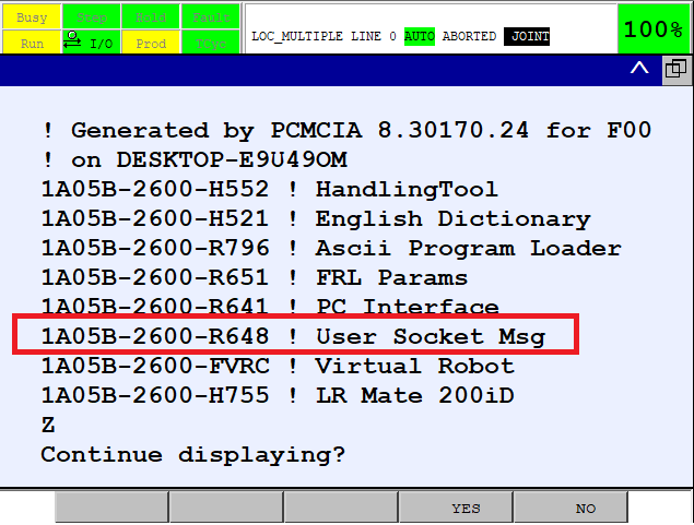
- R648 User Socket Msg - Socket Communication option available
Click Menu -> Next -> Status -> Version ID -> Next -> F3[ORDER FI] to verify that the R648 User Socket Msg option is installed on your robot controller (see figure below):
2. Fanuc Controller Setup
2.1 Set IP Addresses of Ethernet Ports
The first step of the process is to configure the IP addresses of the robot controller.
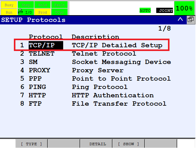
Using Teach Pendant, press Menu -> Setup -> Host Comm -> TCP/IP -> F3[Detail]:
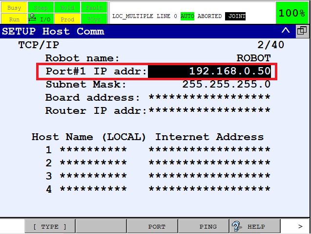
Two Ethernet ports should be available; users are recommended to configure Port#1 for communication with Vision Controller.
Amend the IP address of Port#1 to match your network configuration:
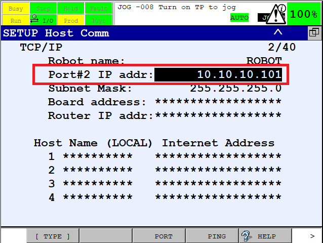
If you use ROBOGUIDE for workcell commissioning, configure Port#2 for transferring files between the robot controller and your PC.
Click F3[PORT] to switch between Port#1 and Port#2 and amend the IP address of Port#2 to match your network configuration:
2.3 Configure TCP/IP Client
The main Photoneo Bin Picking application works in client mode. Configure the TCP/IP Client for this purpose.
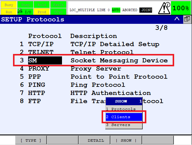
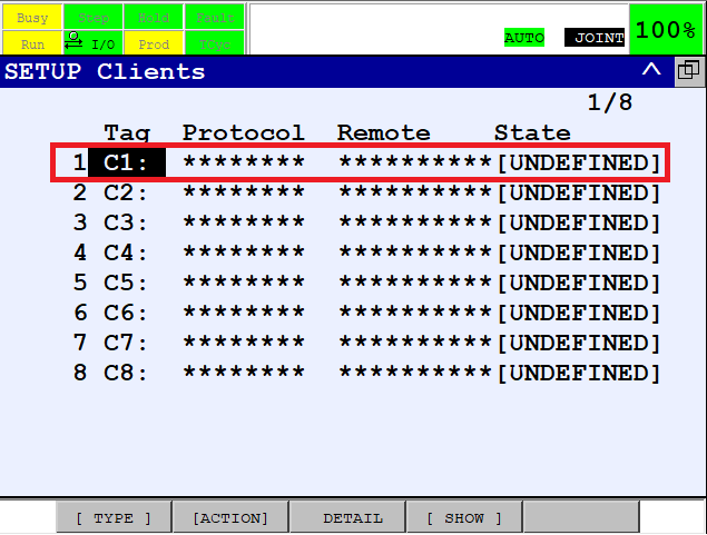
Press Menu -> Setup -> Host Comm -> F4[SHOW] and select Clients
Select C1 slot
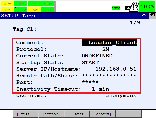
Configure the TCP/IP client C3 as is shown in the figure below:
NOTE: Set the IP address of the Vision Controller to SERVER IP/HOSTNAME
3. Photoneo Fanuc Module Setup
4. Calibration
4.1 Robot Camera Calibration
4.2 Tool Calibration
5. Runtime
5.1 Reteach Start and End poses
5.2 Run Locator
6. TP Program
The Locator Fanuc module is a combination of Karel background routine loc_client.pc and four TP files.
- - loc_client.pc - handles communication with locator and feeding PR with received data
- - LOC_SINGLE.TP - is a basic template for using Locator Fanuc Module in the Single Result Mode
- - LOC_MULTIPLE.TP - is a basic template for using Locator Fanuc Module in the Multiple Result Mode
- - LOC_GRIP_ATT.TP - user should fill this function by commands required for attachning object to the gripper
- - LOC_GRIP_DEA.TP - user should fill this function by commands required for detaching object from the gripper
with the Locator and provides basic examples of how to navigate the robot to specific targets.
6.1 Main
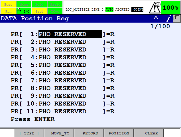
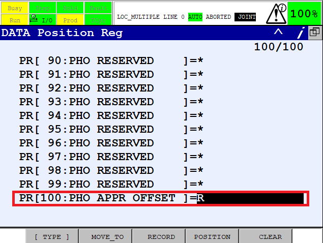
The following code is a content of the LOC_SINGLE.TP. As can be seen in the figure below, it clears registers, runs LOC_CLIENT Karel background routine and waits until karel routine establishes the connection with Locator. As soon as connection is established, Single Result Mode Trigger is sent to Locator. Locator initializes scanning and localization and if a result is found it is being sent back to the Fanuc robot. The Karel routine fills Cartesian Data received from Locator to PR[1] and sets F[RES_RECEIVED] flag to ON. LOC_SINGLE.TP keeps waiting for F[RES_RECEIVED] right after it is set to ON it performs the motion to the received target. Offset from PR[100] is applied for approaching and deapproaching points. After finalizing the placing, scan is repeated. For Multiple Result Mode, scan is repeated after picking all received targets.
  1:  !Clear Registers ;
  2:  F[2]=(OFF) ;
  3:  F[3]=(OFF) ;
  4:  F[4]=(OFF) ;
  5:  R[7:PHO LOC STATUS]=99    ;
  6:  R[8:PHO NUM TAR REQ]=0    ;
  7:  R[9:PHO NUM TAR RCV]=0    ;
  8:  !Start Locator Client ;
  9:  RUN LOC_CLIENT ;
 10:  !Move Out of Scanning Volume ;
 11:J P[1] 100% FINE    ;
 12:  !Wait for Establishing Connectio  ;
 13:  WAIT (F[2]=ON)    ;
 14:  !Main Loop ;
 15:  LBL[1] ;
 16:  !Single Result Trigger ;
 17:  R[6:PHO REQ TYPE]=1    ;
 18:  F[3]=(ON) ;
 19:  !Wait For Response ;
 20:  WAIT (F[4]=ON)    ;
 21:  F[4]=(OFF) ;
 22:  !Repeat Scanning if Timeout ;
 23:  IF (R[7:PHO LOC STATUS]=1),JMP LBL[1] ;
 24:  !If OK, Proceed to Picking ;
 25:J P[2] 100% CNT100    ;
 26:L PR[1:PHO RESERVED] 100mm/sec FINE Offset,PR[100:PHO APPR OFFSET]    ;
 27:L PR[1:PHO RESERVED] 1000mm/sec FINE    ;
 28:  CALL LOC_GRIP_ATT    ;
 29:L PR[1:PHO RESERVED] 100mm/sec FINE Offset,PR[100:PHO APPR OFFSET]    ;
 30:  !Move Out of Scanning Volume ;
 31:J P[3] 100% FINE    ;
 32:  !Placing ;
 33:J P[4] 100% CNT100    ;
 34:J P[5] 100% FINE    ;
 35:  CALL LOC_GRIP_DEA    ;
 36:J P[6] 100% CNT100    ;
 37:  !End of Loop ;
 38:  JMP LBL[1] ;
6.2 Registers Used
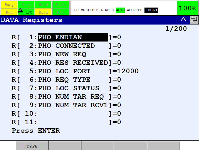
The Locator client uses the following Registers:
- - R1[PHO ENDIAN] - Little/Big Endian Switch Little Endian = 0, Big Endian = 1
- - R1[PHO CONNECTED] - Connection flag, ON - Connected to Locator, OFF - Disconnected from Locator
- - R1[PHO NEW REQ] - New Request Flag - used to synchronize action betweeen TP and Karel programs
- - R1[PHO RES RECEIVED] - Response Recevied Flag - used to synchronize action between TP and Karel programs
- - R1[PHO LOC PORT] - Register for configuring port on Which Locator server is listening
- - R1[PHO REQ TYPE] - Register for storing the Request Type - Single Result Mode = 1, Multiple Result Mode = 2
- - R1[PHO LOC STATUS] - Register for transfering Locator Status Value from Karel to TP, 0 = LOC_OK, 1 = LOC_TIMEOUT, 2 = LOC_ERROR
- - R1[PHO NUM TAR REQ] - Register for storing the number of results requested from Locator (only valid for Multiple Result Mode)
- - R1[PHO NUM TAR RCV] - Register for storing the number of results received from Locator (only valid for Multiple Result Mode)
6.3 Communication Protocol
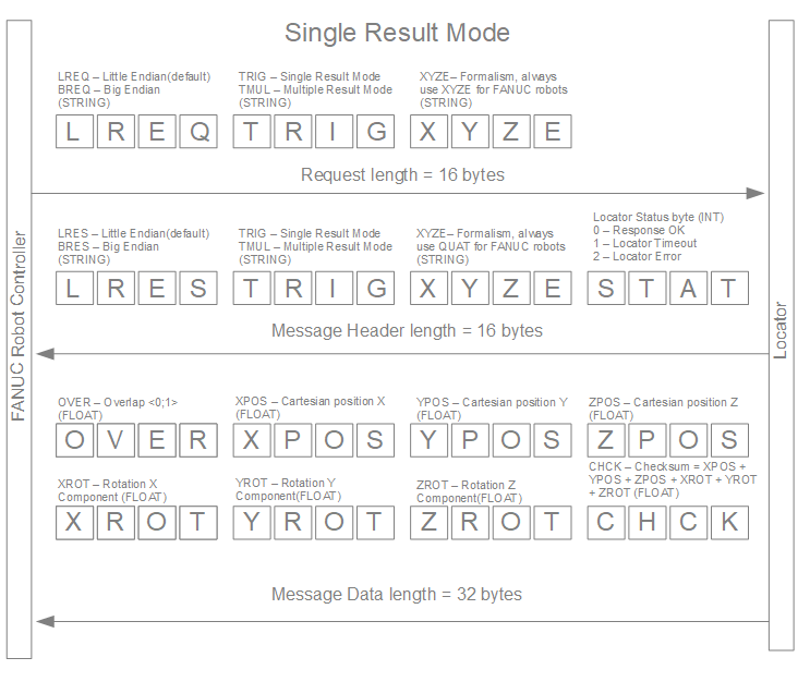
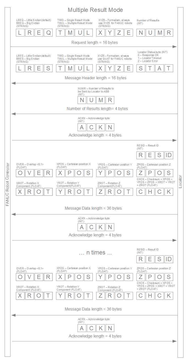
The following illustrations explain the Locator - FANUC communication protocol in both Single and Multiple Result Modes.
NOTE #1: Communication is performed in UF - Unformatted mode
