Difference between revisions of "Bin Picking Tutorial: Setting up Photoneo Bin Picking Studio with STAUBLI robots"
| Line 9: | Line 9: | ||
== 2. CS9 Controller setup == | == 2. CS9 Controller setup == | ||
| − | The following tutorial | + | The following tutorial provides a step by step guide of how to configure your Stäubli CS9 controller and install the VAL3 files you will need to get the robot interface for Photoneo Binpicking Solution up and running. |
=== 2.1 Network configuration === | === 2.1 Network configuration === | ||
| − | + | The first step of the setup is to configure the network interface. | |
| − | Turn on the CS9 Controller, wait for the Initialization Screen to appear, open | + | Turn on the CS9 Controller, wait for the Initialization Screen to appear, open '''Settings''' and select the '''Network''' option: |
| Line 21: | Line 21: | ||
| − | As you can see in the figure below, | + | As you can see in the figure below, two network interfaces are available. |
| − | '''- J204''' is usually used for communication with | + | '''- J204''' is usually used for communication with third party devices, in this case with the Vision Controller. |
| − | '''- J205''' is usually designated for file transfers between Staubli Robotics Suite and | + | '''- J205''' is usually designated for file transfers between the Staubli Robotics Suite and the robot controller. |
| − | + | Input the J205 IP address to meet your network configuration. | |
| Line 34: | Line 34: | ||
== 3 Staubli Robotics Suite == | == 3 Staubli Robotics Suite == | ||
| − | + | It is now time to launch Staubli Robotics Suite and start the SRS project configuration. | |
=== 3.1 Create new project === | === 3.1 Create new project === | ||
| − | Start by creating a new project. Click on '''Home''' tab -> '''New''' -> '''New cell wizard'''. | + | Start by creating a new project. Click on the '''Home''' tab -> '''New''' -> '''New cell wizard'''. |
| − | Type the project name and select the project location. For the | + | Type the project name and select the project location. For the purposes of this tutorial we will use a '''TX2_40''' arm and '''Photoneo_binpicking''' as a project name. |
| Line 46: | Line 46: | ||
| − | If you are already connected to a real robot controller select | + | If you are already connected to a real robot controller select '''Add a local controller from a remote controller'''. |
| Line 52: | Line 52: | ||
| − | In order to select a controller from available targets, click | + | In order to select a controller from the available targets, click the '''"..."''' button |
| Line 58: | Line 58: | ||
| − | In the '''General Information''' section type '''J205 IP address''' of robot controller. | + | In the '''General Information''' section type input the '''J205 IP address''' of the robot controller. |
| − | Remote Connection section contains authorization information. | + | The Remote Connection section contains authorization information. Input the following credentials for accessing controller: |
'''User Name:''' maintenance. | '''User Name:''' maintenance. | ||
| Line 68: | Line 68: | ||
Port : '''5653''' | Port : '''5653''' | ||
| − | Hit '''OK''' | + | Hit '''OK''' and if everything works properly you should see the following dialog window: |
| Line 76: | Line 76: | ||
=== 3.2 Copy VAL3 applications === | === 3.2 Copy VAL3 applications === | ||
| − | If connection | + | If connection has been established properly, you are ready to copy the VAL3 files containing the Photoneo Staubli interface to your project. |
| − | Photoneo Staubli interface consists of | + | The Photoneo Staubli interface consists of three folders - '''photoneo_common''', '''customer_definitions''' and '''main_application'''. |
| − | Copy these folders from Photoneo | + | Copy these folders from the Photoneo Staubli Module archive (.zip file) which you received with Photoneo BP solution to the '''usrapp''' folder of your project '''(Project_name\Controller_name\usr\usrapp\ )'''. |
| − | Now open Cell Explorer in Staubli Robotics Suite and add existing applications to the project. | + | Now open Cell Explorer in Staubli Robotics Suite and add the existing applications to the project. |
| − | Expand '''Project_name''', | + | Expand '''Project_name''', right click on '''Controller_name''', select '''Open Application''' and load all three applications (select '''.pjx''' files). |
| Line 97: | Line 97: | ||
=== 3.3 Edit fBaseLink === | === 3.3 Edit fBaseLink === | ||
| − | Cartesian origin of Staubli robots '''is different''' than Cartesian origin of robot models used in Photoneo Binpicking System. In order to | + | The Cartesian origin of Staubli robots '''is different''' than the Cartesian origin of robot models used in the Photoneo Binpicking System. In order to ensure successful calibration, an additional frame with a predefined offset in Z axis must be created. |
| − | In Cell Explorer, switch to Data tab, under controller expand '''photoneo_common'''->'''frame''' and double click on '''fBaseLink'''. Edit | + | In Cell Explorer, switch to the Data tab, under controller expand '''photoneo_common'''->'''frame''' and double click on '''fBaseLink'''. Edit the Z axis value according to the arm you are using for your application. |
| Line 105: | Line 105: | ||
| − | + | A table of offsets for specific robot models is shown in the figure below: | |
| Line 112: | Line 112: | ||
=== 3.4 Socket configuration === | === 3.4 Socket configuration === | ||
| − | + | In order to ensure proper communication with the Vision Controller, two sockets (one server and one client) need to be configured. | |
| − | On the '''Home''' tab click on '''Physical IO's''' | + | On the '''Home''' tab click on '''Physical IO's'''. In the IO table, right click on '''Sockets''' -> '''Edit Board''' |
| Line 120: | Line 120: | ||
| − | First add '''Tcp_client''' which is used for transfering bin picking requests and responses between robot and vision controller. | + | First add '''Tcp_client''' which is used for transfering bin picking requests and responses between robot and the vision controller. |
| Line 126: | Line 126: | ||
| − | Use following values: | + | Use the following values: |
'''Name:''' PhotoneoClient | '''Name:''' PhotoneoClient | ||
| Line 140: | Line 140: | ||
'''Server IP:''' IP address of Vision Controller, which choosen in the Photoneo Binpicking Studio | '''Server IP:''' IP address of Vision Controller, which choosen in the Photoneo Binpicking Studio | ||
| − | + | Click '''OK''' to apply the changes | |
| Line 146: | Line 146: | ||
| − | Now add '''Tcp_server''' with following values: | + | Now add '''Tcp_server''' with the following values: |
'''Name:''' PhotoneoStateServer | '''Name:''' PhotoneoStateServer | ||
| Line 154: | Line 154: | ||
'''End of String:''' 10 | '''End of String:''' 10 | ||
| − | + | Click '''OK''' to apply the changes | |
| Line 160: | Line 160: | ||
| − | + | We now need to create two '''sio''' variables and link them with existing sockets. | |
| − | Using Cell Explorer switch to Data tab and check two '''sio''' variables - '''sPHOCLIENT''' and '''sPHOSTATE'''. | + | Using Cell Explorer switch to the Data tab and check two '''sio''' variables - '''sPHOCLIENT''' and '''sPHOSTATE'''. |
| − | In order to link sio variables with existing sockets, double click on '''sPHOCLIENT''' and select '''Sockets\PhotoneoClient''' socket in the '''IO field'''. | + | In order to link sio variables with existing sockets, double click on '''sPHOCLIENT''' and select the '''Sockets\PhotoneoClient''' socket in the '''IO field'''. |
Repeat the same procedure with '''sPHOSTATE''' and '''Sockets\PhotoneoStateServer'''. | Repeat the same procedure with '''sPHOSTATE''' and '''Sockets\PhotoneoStateServer'''. | ||
| − | + | You should now see that both variables are linked to physical IOs as is shown in the picture below: | |
| Line 175: | Line 175: | ||
=== 3.5 Binpicking Start and End poses === | === 3.5 Binpicking Start and End poses === | ||
| − | + | A crucial step of binpicking configuration is the configuration of bin picking home, start, and end poses. | |
| − | Using Cell Explorer switch to Data tab and edit 3 jointRx variables - '''jStartPose''', '''jEndPose''', '''jHomePose''' ( | + | Using Cell Explorer switch to the Data tab and edit 3 jointRx variables - '''jStartPose''', '''jEndPose''', '''jHomePose''' (you can find jHomePose in the main_application) |
| − | Set joint values of JStartPose, jEndPose and jHomePose to meet your application requirements. | + | Set the joint values of JStartPose, jEndPose and jHomePose to meet your application requirements. |
| Line 185: | Line 185: | ||
| − | + | The initial steps of the SRS project configuration are now complete. '''Save the cell''' and you are ready to transfer the project files to the robot controller. | |
=== 3.6 Transfer files === | === 3.6 Transfer files === | ||
Revision as of 07:20, 21 May 2018
Contents
1. Prerequisities
Photoneo Stäubli Interface was developed using the latest CS9 controler version s8.4.2Cs9BS1099.
It should be compatible with older CS8 controllers with several (mostly UI related) changes.
NOTE: Use of Stäubli Robotics Suite 2016.6.1 or higher is highly recommended for Photoneo Stäubli Interface setup.
2. CS9 Controller setup
The following tutorial provides a step by step guide of how to configure your Stäubli CS9 controller and install the VAL3 files you will need to get the robot interface for Photoneo Binpicking Solution up and running.
2.1 Network configuration
The first step of the setup is to configure the network interface.
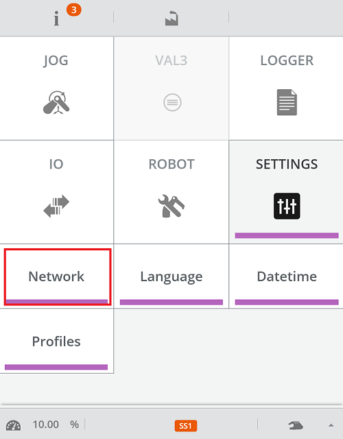
Turn on the CS9 Controller, wait for the Initialization Screen to appear, open Settings and select the Network option:
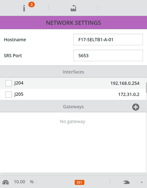
As you can see in the figure below, two network interfaces are available.
- J204 is usually used for communication with third party devices, in this case with the Vision Controller.
- J205 is usually designated for file transfers between the Staubli Robotics Suite and the robot controller.
Input the J205 IP address to meet your network configuration.
3 Staubli Robotics Suite
It is now time to launch Staubli Robotics Suite and start the SRS project configuration.
3.1 Create new project
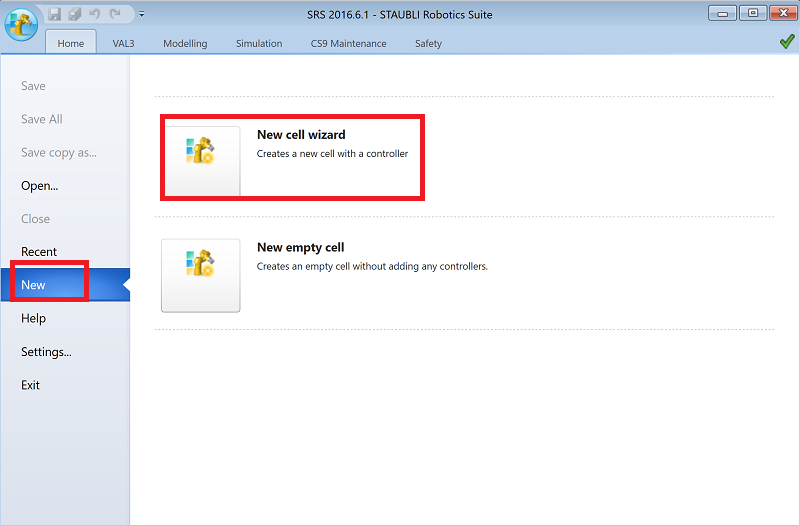
Start by creating a new project. Click on the Home tab -> New -> New cell wizard.
Type the project name and select the project location. For the purposes of this tutorial we will use a TX2_40 arm and Photoneo_binpicking as a project name.
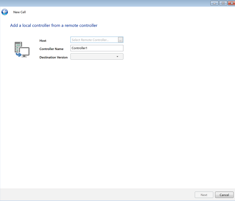
If you are already connected to a real robot controller select Add a local controller from a remote controller.
In order to select a controller from the available targets, click the "..." button
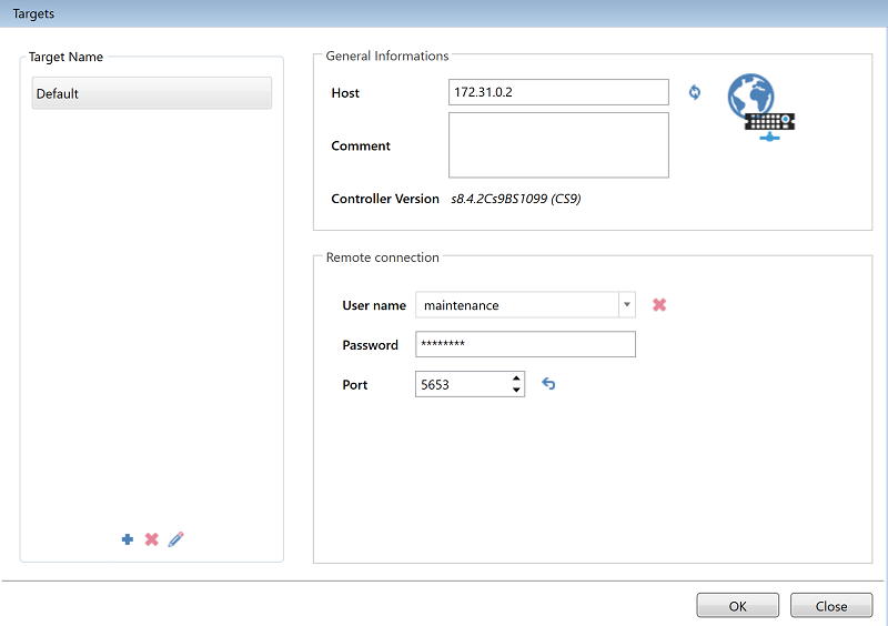
In the General Information section type input the J205 IP address of the robot controller.
The Remote Connection section contains authorization information. Input the following credentials for accessing controller:
User Name: maintenance.
Password: spec_cal
Port : 5653
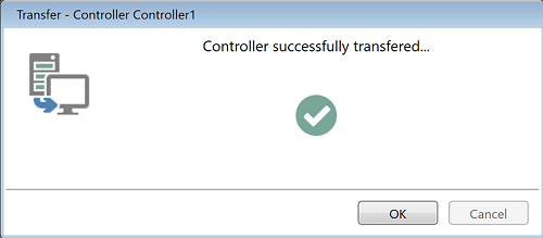
Hit OK and if everything works properly you should see the following dialog window:
3.2 Copy VAL3 applications
If connection has been established properly, you are ready to copy the VAL3 files containing the Photoneo Staubli interface to your project.
The Photoneo Staubli interface consists of three folders - photoneo_common, customer_definitions and main_application.
Copy these folders from the Photoneo Staubli Module archive (.zip file) which you received with Photoneo BP solution to the usrapp folder of your project (Project_name\Controller_name\usr\usrapp\ ).
Now open Cell Explorer in Staubli Robotics Suite and add the existing applications to the project.
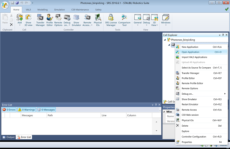
Expand Project_name, right click on Controller_name, select Open Application and load all three applications (select .pjx files).
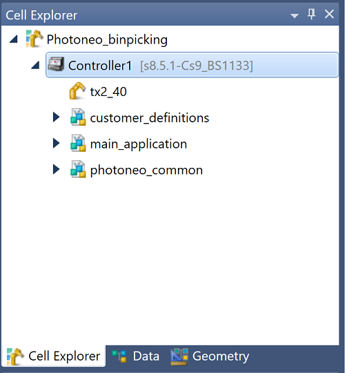
The resulting project structure is shown in the figure below:
3.3 Edit fBaseLink
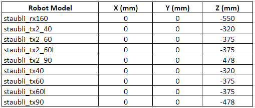
The Cartesian origin of Staubli robots is different than the Cartesian origin of robot models used in the Photoneo Binpicking System. In order to ensure successful calibration, an additional frame with a predefined offset in Z axis must be created.
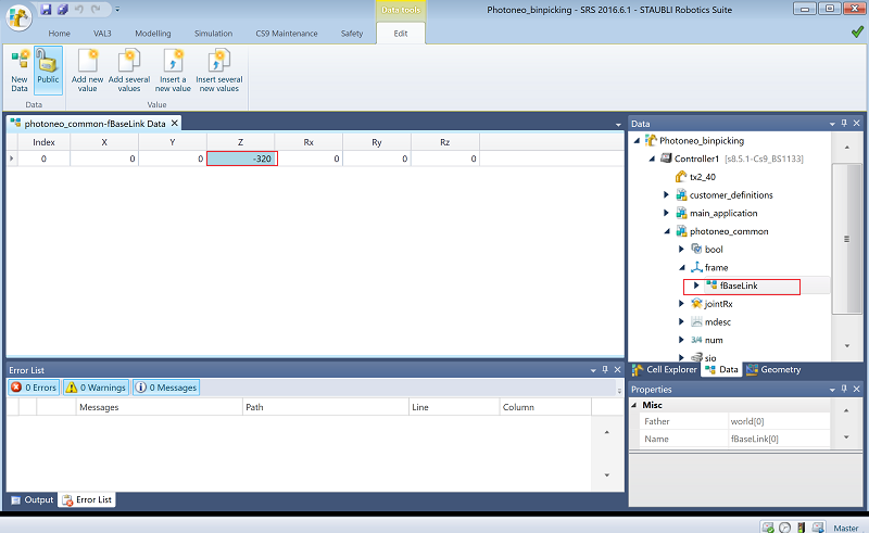
In Cell Explorer, switch to the Data tab, under controller expand photoneo_common->frame and double click on fBaseLink. Edit the Z axis value according to the arm you are using for your application.
A table of offsets for specific robot models is shown in the figure below:
3.4 Socket configuration
In order to ensure proper communication with the Vision Controller, two sockets (one server and one client) need to be configured.
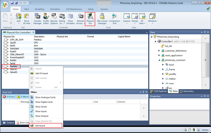
On the Home tab click on Physical IO's. In the IO table, right click on Sockets -> Edit Board
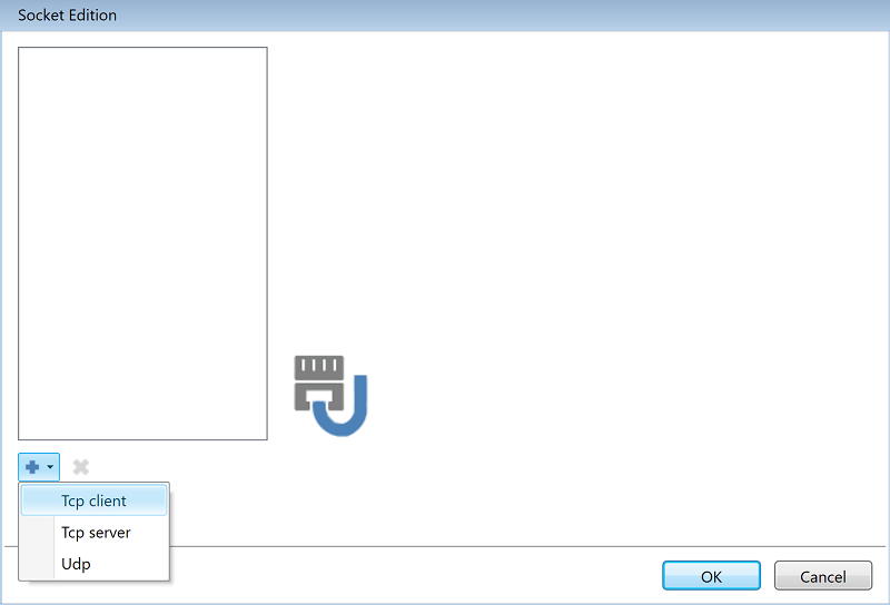
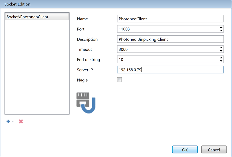
First add Tcp_client which is used for transfering bin picking requests and responses between robot and the vision controller.
Use the following values:
Name: PhotoneoClient
Port: 11003
Description: Photoneo Binpicking Client
Timeout: 3000
End of String: 10
Server IP: IP address of Vision Controller, which choosen in the Photoneo Binpicking Studio
Click OK to apply the changes
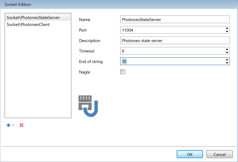
Now add Tcp_server with the following values:
Name: PhotoneoStateServer Port: 11004 Description: Photoneo State Server Timeout: 0 End of String: 10
Click OK to apply the changes
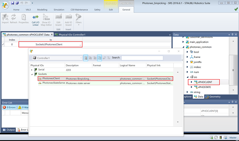
We now need to create two sio variables and link them with existing sockets.
Using Cell Explorer switch to the Data tab and check two sio variables - sPHOCLIENT and sPHOSTATE.
In order to link sio variables with existing sockets, double click on sPHOCLIENT and select the Sockets\PhotoneoClient socket in the IO field.
Repeat the same procedure with sPHOSTATE and Sockets\PhotoneoStateServer.
You should now see that both variables are linked to physical IOs as is shown in the picture below:
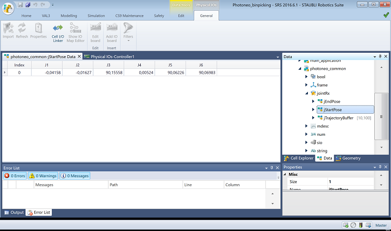
3.5 Binpicking Start and End poses
A crucial step of binpicking configuration is the configuration of bin picking home, start, and end poses.
Using Cell Explorer switch to the Data tab and edit 3 jointRx variables - jStartPose, jEndPose, jHomePose (you can find jHomePose in the main_application)
Set the joint values of JStartPose, jEndPose and jHomePose to meet your application requirements.
The initial steps of the SRS project configuration are now complete. Save the cell and you are ready to transfer the project files to the robot controller.
3.6 Transfer files
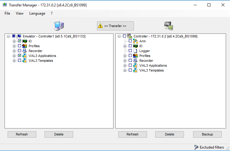
On the Home tab click on the Transfer Manager button and select target robot controller.
If connection between SRS and robot controller was established properly, a transfer manager dialog window should appear.
We have done changes to IO and VAL3 Applications so make sure that these items are checked before transferring files.
3.7 Load Application
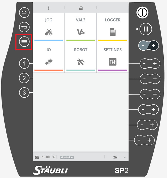
If project has been transferred to the robot controller successfully, it has to be loaded using pendant. With the current system version this is achieved using the "old menu" from previous controller version.
Start by clicking the button shown in the picture below:
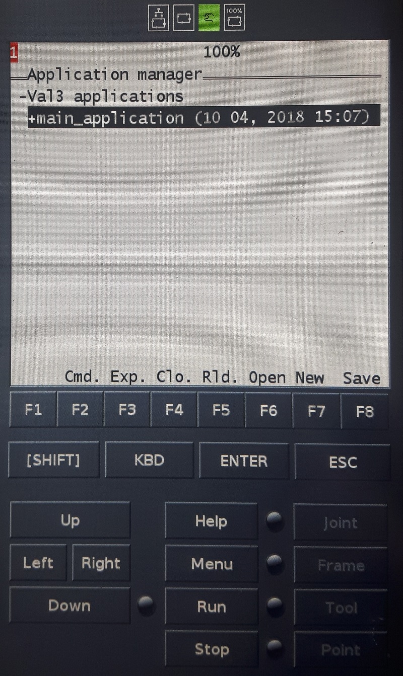
In the old menu select Application manager -> Val3 applications -> main_application -> F6 (open)
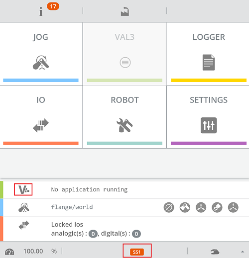
Return back to the "color menu" by pressing Home button. Now open VAL3 Applications menu.
Click the bottom label and select "V" letter on the widget as shown in the picture below:
You should see main_application is now available in the application list.
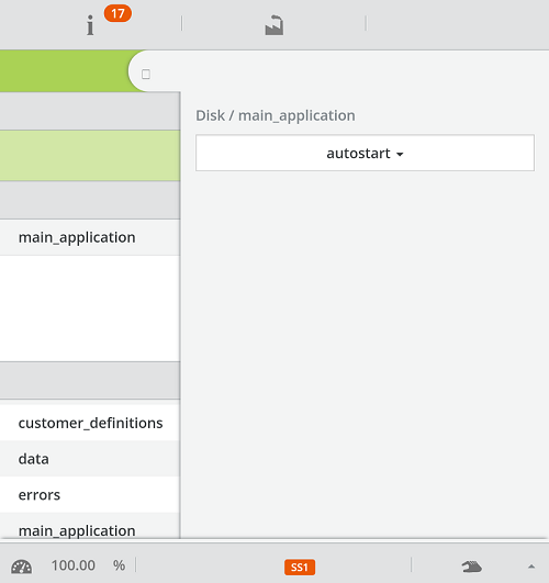
As the last step, we need to make main_application to start automatically. Click main_application and set autostart mode.
At this point your Robot Controller is configured to work with Photoneo Binpicking Solution. However you should adopt VAL3 code to meet your application requirements better - you might need to reteach HOME, START and END poses, update part placing, application logic, etc. The following section of the tutorial provides basic examples of how this can be programmed as well as a detailed explanation of Photoneo VAL3 API.
4. VAL3
Photoneo Staubli interface was designed to be easily integrated into existing application written in VAL3 code. It provides two means which influence the final robot behavior:
- VAL3 API - set of VAL3 requests (or procedures) used to control the bin picking sequence. Requests are defined in photoneo_common application and used within main_module application
- VAL3 CONFIG - customer_definitions holds an application specific settings such as gripper commands, motion speed, precision and overall bin picking sequence definition.
4.1 VAL3 API
The following API describes the functionality of requests provided by Photoneo Stabli Interface. These requests are intended for high level control of bin picking sequences and are usually called in main_module application.
pho_request_init() - request to initialize bin picking application from the Vision Controller side. Start and End Poses defined by the operator from thephotoneo_common in chapter 3.5 side are transferred to the Vision Controller and used in the trajectory planning pipeline as start and terminus points.
wait_for_server() - optional function to check if a connection to the Vision Controller has been established.
scan_request() - request to trigger the next scan and localization. Non-blocking request; the VAL3 program continues immediately at the next line.
wait_for_scan_completition() - function to wait for scan to be finished. This should be called after triggering the scan, but not immediately
trajectory_request() - request to start trajectory planning for current goal. Non-blocking function; the VAL3 program continues immediately at the next line.
trajectory_receive() - function to receive requested bin picking trajectories (consisting of a sequence of trajectory and gripper operations). This is usually called inside pick_part() function by default. Blocking function; waits for motion data to be received.
calib_add_point_request() - request to add calibration point - a scan is triggered and the calibration is recalculated. Blocking request; the program will not continue until the calibration result is recalculated and has been received by the Robot Controller.
calib_set_to_scanner_request() - request to set current calibration result to the PhoXi Scanner
calib_reset_request() - request to reset current calibration and remove all previously added points
pick_part() - request to execute bin picking operation. This usually receives the requested trajectory and performs motion execution. Blocking function; the program does not continue until the whole sequence is finished. Always make sure that the robot is in photoneo_common:jStartPose before calling this function.
4.2 VAL3 CONFIG
customer_definitions enables the user to configure several bin picking settings, including gripper command implementations, trajectory speed and precision adjustments.
- gripper_attach() - implement function for opening your gripper here
- griper_detach() - implement function for closing your gripper here
- gripper_user_1() - implement custom user gripper command (reserved for future use)
- gripper_user_2() - implement custom user gripper command (reserved for future use)
- gripper_user_3() - implement custom user gripper command (reserved for future use)
- gripper_user_4() - implement custom user gripper command (reserved for future use)
- gripper_user_5() - implement custom user gripper command (reserved for future use)
- gripper_user_6() - implement custom user gripper command (reserved for future use)
- pick_part() - standard bin picking sequence. This flexible, operation-based implementation allows performing bin picking sequences, which consist of various numbers of operations to be performed. Do not edit !!!
- customer_definitions:mPickingSpeed which is type mdesc is used to define speed and path approximations for Picking Path Stages as defined in Photoneo Binpicking Web Interface. Define trajectory speed and precision of Approach trajectory on the first line, for a Grasp trajectory on the second line and so on ... See the table below for better understanding:
4.3 VAL3 ERROR HANDLING
Photoneo BP solution provides basic error handling. If an error occurs during bin picking operations the photoeno_common:nErrCode variable contains the code of the specific error which will helps to identify the source of the problem.
photonoe_common:nERR_OK := 0 - Service response from Vision Controller is valid
photonoe_common:nERR_SERVICE := 1 - Service response from Vision Controller is invalid.
photonoe_common:nERR_UNKNOWN_REQ := 2 - The Vision Controller received an unknown request.
photonoe_common:nERR_COM_FAILURE := 3 - Communication failure due to socket closure.
photonoe_common:nERR_BAD_DATA := 4 - Data validation check has failed.
photonoe_common:nERR_TIMEOUT := 5 - Communication failure due to socket timeout.
photonoe_common:nERR_PLANNING_FAILED := 201 - Trajectory planning has failed
photonoe_common:nERR_NO_PART_FOUND := 202 - No part has been localized
photonoe_common:nERR_NOT_INITIALIZED := 203 - Bin picking application has not been properly initialized on Vision Controller
photonoe_common:nERR_PART_LOST := 204 - Part has been lost during motion execution
photonoe_common:nERR_UNKNOWN_ERR := 299 - Unspecified internal error
4.4 main_module application
The following section provides a detailed explanation of main_application - the module through which the user's application and Photoneo Bin Picking API are integrated together.
4.4.1 start()
The start() procedure is simply a selection of which particular task is about to be executed.
Comment PHOMAIN task in order to execute calibration procedure or comment PHOCALIB task if you want to execute bin picking.
   begin
     //----------------------------------------------------------------------
     // Copyright (c) 2018 Photoneo s.r.o.
     // All rights reserved
     // Description: Photoneo Staubli Module v.1.2.0 -  Start()
     //----------------------------------------------------------------------
     call photoneo_common:start()

     // Start PHOMAIN task
     // Comment this code, when you can calibrate
     if((taskStatus("PHOMAIN") == -1))
       taskCreate "PHOMAIN", 50, main()
     endIf
     // Start PHOCALIB task
     // Uncomment this code when you can calibrate
     //if((taskStatus("PHOCALIB") == -1))
     //  taskCreate "PHOCALIB", 50, calibration()
     //endIf
     // Start WATCHDOG task
     if((taskStatus("WATCHDOG") == -1))
       taskCreate "WATCHDOG", 50, watchdog_main()
     endIf
   end
4.4.2 main()
This is a basic bin picking template. The main program loop is defined here. Adopt application login and placing part of the code to meet specific workcell and application requirements.
   begin
     //-------------------------------------------------------------------------------------------------------
     // Copyright (c) 2018 Photoneo s.r.o.
     // All rights reserved
     // Description: Photoneo Staubli Module v.1.2.0 - Main Module
     //              This is a basic bin picking template. The main program loop is defined here.
     //              Adopt application login and placing procedure here to meet your application requirements
     //-------------------------------------------------------------------------------------------------------
     // Clear error counter for err_handling procedure
     l_nErrorCounter = 0

     //  Wait for connection to the the Vision Controller
     call photoneo_common:wait_for_server()

     // Send bin picking initialization request to the Vision Controller,
     call photoneo_common:initialize_request()

     // Move robot away from scanning area - reteach this position for your robot and workcell
     movej(jHomePose, flange, mNomSpeed)
     waitEndMove()

     // When robot is away from scanning area, trigger first scan and localization
     call photoneo_common:scan_request()
     while true

       //==================== PHOTONEO BIN PICKING START ===========================
       // wait until scanning is completed
       call photoneo_common:wait_for_scan_completition()

       // Check Error Status
       if(photoneo_common:nErrCode == photoneo_common:nOK)

         // Trigger trajectory planning
         call photoneo_common:trajectory_request()

         // While trajectory is being calculated, move robot to bin picking start position
         movej(photoneo_common:jStartPose, flange, mNomSpeed)

         // Calculated trajectory is received here
         call photoneo_common:trajectory_receive()
       endIf

       // Check Error Status
       if(photoneo_common:nErrCode == photoneo_common:nOK)

         // If trajectory is valid pick part execute bin picking application
         call customer_definitions:pick_part()

         //=================== PHOTONEO BIN PICKING END ===========================

         // Clear error counter if result is ok
         l_nErrorCounter = 0

         //==================== PLACING START ==================================
         // Adopt code for placing operations
         movej(jHomePose, flange, mNomSpeed)
         waitEndMove()
         // Triger next scan and localization, trajectory for next cycle is calculated while object is being placed
         call photoneo_common:scan_request()
         call place_part()
         //==================== PLACING END ==================================
       else

         //====================== ERROR HANDLING START =======================
         // In case of communication failure, main_application is terminated immediately
         if(photoneo_common:nErrCode == photoneo_common:nERR_COM_FAILURE)
           popUpMsg("Communication failure")
           movej(jHomePose, flange, mNomSpeed)
           waitEndMove()
           return

         //If bin picking service returned error response, reinitialize and trigger new scan (Adopt if needed)
         elseIf(photoneo_common:nErrCode == photoneo_common:nERR_SERVICE or photoneo_common:nErrCode == photoneo_common:nERR_NOT_INITIALIZED)
           popUpMsg("Service error from VC")
           movej(jHomePose, flange, mNomSpeed)
           waitEndMove()
           return
           delay(10)
           call photoneo_common:initialize_request()
           call photoneo_common:scan_request()

         //  If planning failed or no part was found, notify user and continue by next scan (Adopt if needed)
         elseIf(photoneo_common:nErrCode == photoneo_common:nERR_PLANNING_FAILED or photoneo_common:nErrCode == photoneo_common:nERR_NO_PART_FOUND)
           popUpMsg("No part found or planning failed")
           movej(jHomePose, flange, mNomSpeed)
           waitEndMove()
           call photoneo_common:scan_request()
         endIf

         l_nErrorCounter = l_nErrorCounter + 1
         if(l_nErrorCounter > 2)
           return
         endIf
         //====================== ERROR HANDLING END =========================
       endIf
     endWhile
   end
4.4.3 calibration()
Reteach calibration positions and call pho_request_calib_add_point() requests after reaching each calibration pose. Users are recommended to run calibration in MANUAL mode in order to have full control over the process.
Always make sure that the robot does not collide with the workcell during transitions between specific waypoints.
    begin
     //------------------------------------------------------------------------------------------------------------------------
     // Copyright (c) 2018 Photoneo s.r.o.
     // All rights reserved
     // Description: Photoneo Staubli Module v.1.2.0 -  Calibration Routine
     //              Reteach points and use as many as you need
     //              It it recommended to run calibration in MANUAL mode step by step to have a proper control over the process.
     //              Always make sure that robot does not collide with workcell during transitions between specific waypoints
     //------------------------------------------------------------------------------------------------------------------------

     movej(jCalib1, flange, mNomSpeed)
     waitEndMove()
     call photoneo_common:printLog("Calibration Point 1 reached", "CLIENT")
     call photoneo_common:calib_add_point_request()

     movej(jCalib2, flange, mNomSpeed)
     waitEndMove()
     call photoneo_common:printLog("Calibration Point 2 reached", "CLIENT")
     call photoneo_common:calib_add_point_request()

     movej(jCalib3, flange, mNomSpeed)
     waitEndMove()
     call photoneo_common:printLog("Calibration Point 3 reached", "CLIENT")
     call photoneo_common:calib_add_point_request()

     movej(jCalib4, flange, mNomSpeed)
     waitEndMove()
     call photoneo_common:printLog("Calibration Point 4 reached", "CLIENT")
     call photoneo_common:calib_add_point_request()

     movej(jCalib5, flange, mNomSpeed)
     waitEndMove()
     call photoneo_common:printLog("Calibration Point 4 reached", "CLIENT")
     call photoneo_common:calib_add_point_request()

     call photoneo_common:calib_set_to_scanner_request()

   end
4.4.5 watchdog_main() and error handling
Several error situations might occur during bin picking procedures. Some problems are more serious, some less. For example, if no part is found or the trajectory planning fails, the program simply attempts to repeat the whole sequence. However, if a communication failure is detected, the program is halted immediately. photoneo_common:nErrCode contains the error state from the last response from the Vision Controller. Example of Error handling is described in chapter 4.4.2
IMPORTANT: If error occurs during binpicking procedure, robot moves to home position and halt PHOMAIN task. Watchdog monitors state of PHOMAIN() every second and restart this task imediately.
   begin
     //------------------------------------------------------------------------------------------------------------------------
     // Copyright (c) 2018 Photoneo s.r.o.
     // All rights reserved
     // Description: Photoneo Staubli Module v.1.2.0 -  Watchdog
     //              Monitor PHOMAIN task status and restart task after crash
     //------------------------------------------------------------------------------------------------------------------------

     while(true)
       // Check PHOMAIN State
       if((taskStatus("PHOMAIN") == -1))
           popUpMsg("Main program is down! Restarting...")
         taskCreate "PHOMAIN",   50, main()
       endIf
       // Check Tasks State Every Second
       delay(1)
     endWhile
   end
5. Runtime
Now you are ready to start the binpicking application. Save the Cell, transfer all changes to the robot controller using Transfer Manager tool, and reload the application using the "old menu".
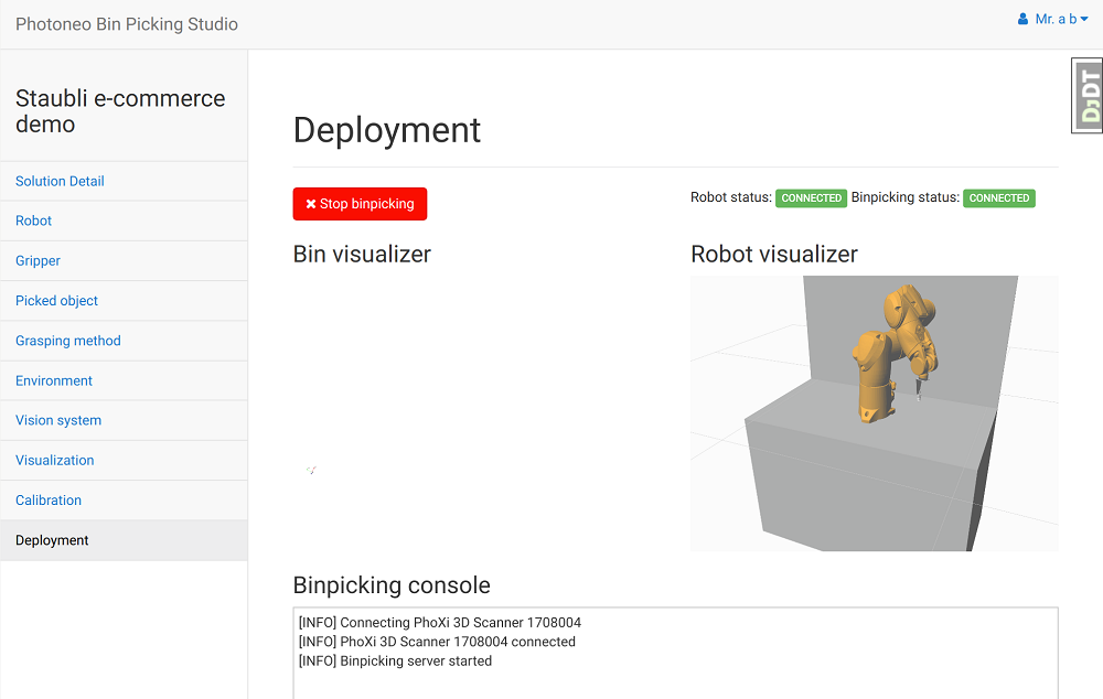
Make sure that the Bin Picking application on the Vision Controller side is running and waiting for a connection.
Switch controller to Auto mode, press Reset button if Safety Restart is needed and launch the main_application.
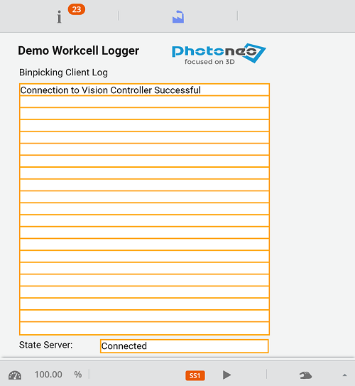
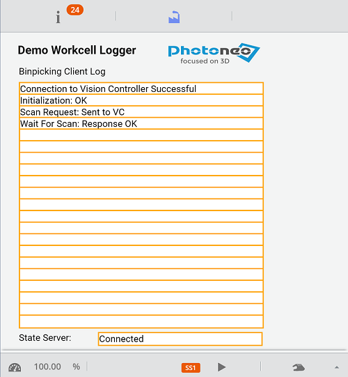
If a connection to Vision Controller was established properly you should see following information on logging screen:
You should also receive the notification that the Vision Controller has established a successful connection to the robot controller:
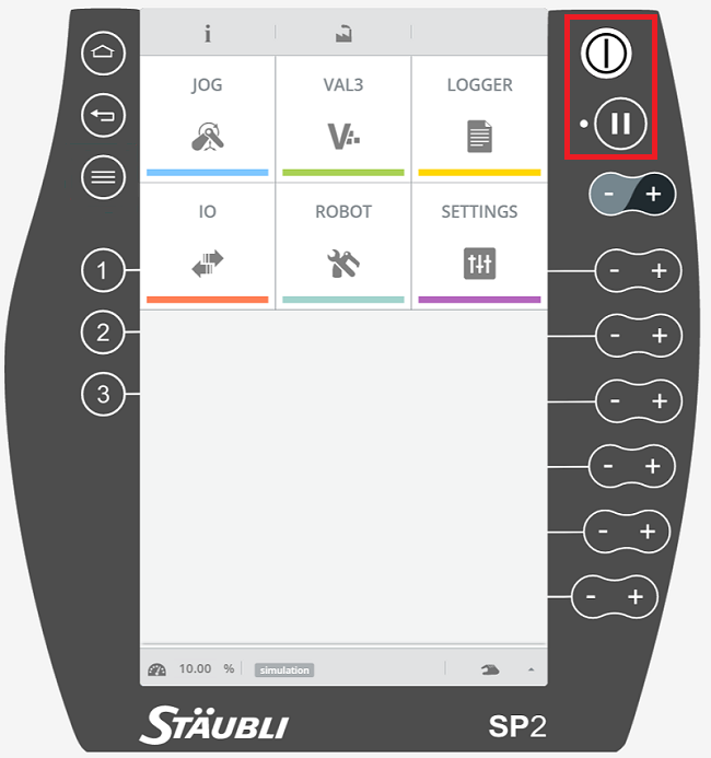
According to the current robot controller mode you might need to press the Power (Button I) and the Play (Button II) in order to enable motion execution
Robot controller should start sending requests to the Vision controller and executing first binpicking movements. See logging screen on Pendant for information about the procedure:
NOTE: Make sure that you are ready to halt motion execution immediately. It is highly recommended to decrease the speed to 10% of maximum during initial bin picking tests.
