Difference between revisions of "Bin Picking Tutorial: Setting up Photoneo Bin Picking Studio with FANUC robots"
| Line 1: | Line 1: | ||
== 1. Prerequisites == | == 1. Prerequisites == | ||
| − | Please make sure that your Fanuc controller | + | Please make sure that your Fanuc controller meets following criteria: |
- '''R632 Karel''' - Karel option | - '''R632 Karel''' - Karel option | ||
Revision as of 21:26, 24 December 2017
Contents
1. Prerequisites
Please make sure that your Fanuc controller meets following criteria:
- R632 Karel - Karel option
- R648 User Socket Msg - Socket Communication option
- System version 8.10 and higher (Versions 6.40 - 7.70 are also supported with certain limitations)
2. Fanuc Controller Setup
2.1 Set IP Address
Turn on the robot controller and set the controller IP address to meet your network configuration.
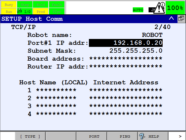
On Pendant Press Menu -> Setup -> Host Comm -> TCP/IP and enter IP address:
Plug Ethernet cable to appropriate socket in the Fanuc controller cabinet, restart the robot controller and try to ping
robot controller from the Vision Controller. If simple ping works, you can proceed to the configuration of robot controller communication.
2.2 Configure State Server
Now we will configure communication server for reporting current joint and tool poses to the Vision Controller
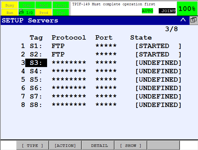
On Pendant press Menu -> Setup -> Host Comm -> F4[SHOW] -> Servers. Following list should appear:
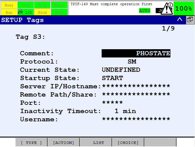
Enter S3 settings and configure PHOSTATE as shown in the figure below:
Now, we need to set the server port which will be utilized for the communication.
Using pendant navigate to Menu -> Next -> System -> Variables.
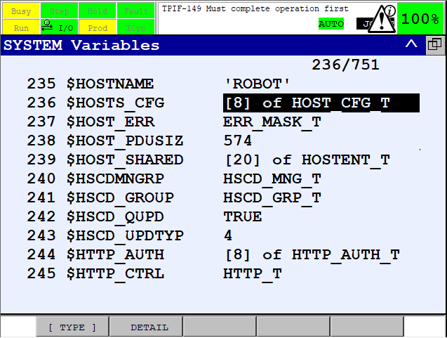
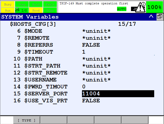
Hold SHIFT to speed up scrolling and press ARROW DOWN several times to find - HOSTS_CFG as shown in the figure below:
For State Server - S3 set SERVER_PORT system variable to 11004. (Be careful! SERVER_PORT and PORT are different items!)
2.3 Configure Binpicking Client
As a next step we will configure communication client for transferring requests/responses between the Vision and Fanuc Controller.
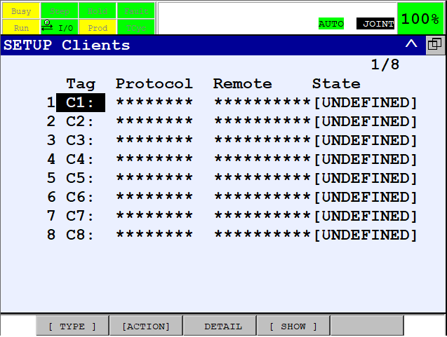
On Pendant press Menu -> Setup -> Host Comm -> F4[SHOW] -> Clients. Following list should appear:
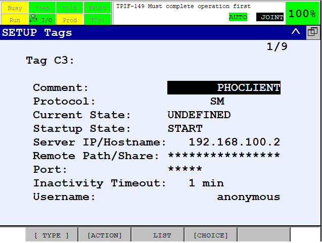
Enter C3 settings and configure PHOCLIENT as shown in the figure below.
Do not forget to input an IP address of Vision Controller Server here!
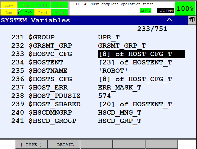
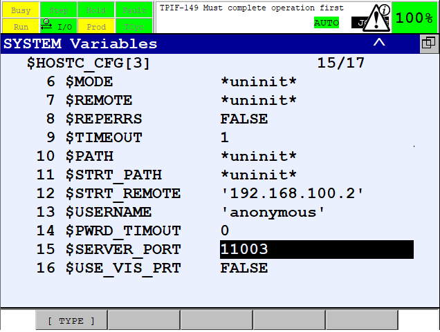
Hold SHIFT to speed up scrolling and press ARROW DOWN several times to find HOSTC_CFG as shown in the figure below
For C3 set SERVER_PORT system variable to 11003 (Be careful! SERVER_PORT and PORT are different items!)
