Difference between revisions of "Bin Picking Tutorial: Setting up Photoneo Bin Picking Studio with ABB robots"
| Line 154: | Line 154: | ||
| − | == 4. | + | == 4. RAPID == |
| − | |||
| − | + | ||
| + | === 4.1 RAPID & Bin Picking Control === | ||
| + | Following API described functionality of requests provided by Photoneo ABB Interface. They are intended for high level control of bin picking sequence and usually called in MainModule.mod. | ||
'''pho_request_init(jointtarget pho_start_bin_picking_pose, jointtarget pho_end_bin_piking_pose)''' - request to initialize bin picking application on the Vision Controller side. Start and End Pose defined by the operator on the RAPID side are transferred to the Vision Controller and used in the trajectory planning pipeline as a start and terminus points. | '''pho_request_init(jointtarget pho_start_bin_picking_pose, jointtarget pho_end_bin_piking_pose)''' - request to initialize bin picking application on the Vision Controller side. Start and End Pose defined by the operator on the RAPID side are transferred to the Vision Controller and used in the trajectory planning pipeline as a start and terminus points. | ||
| Line 170: | Line 171: | ||
'''pho_receive_trajectory()''' - function to receive requested trajectory. This is usually called inside pho_bin_picking() function by default. Blocking function. | '''pho_receive_trajectory()''' - function to receive requested trajectory. This is usually called inside pho_bin_picking() function by default. Blocking function. | ||
| − | '''pho_request_scan_and_traj()''' - function to trigger scan, localization and trajectory planning in a single shot. Blocking function, handy for initial bin picking experiments | + | '''pho_request_scan_and_traj()''' - function to trigger scan, localization and trajectory planning in a single shot. Blocking function, handy for initial bin picking experiments. Dor real production it is more convenient to split this sequence into particular actions and call them accordingly. |
'''pho_request_calib_add_point()''' - request to add calibration point - scan is triggered and calibration is recalculated. Blocking request, program does not continue until calibration result is recalculated and received by the robot controller. | '''pho_request_calib_add_point()''' - request to add calibration point - scan is triggered and calibration is recalculated. Blocking request, program does not continue until calibration result is recalculated and received by the robot controller. | ||
| Line 181: | Line 182: | ||
| − | + | === 4.2 RAPID & Bin Picking Configuration | |
CustomerDefinitions.mod | CustomerDefinitions.mod | ||
Revision as of 23:09, 19 January 2018
1. Prerequisities
In order to get Photoneo ABB Interface running on your ABB IRC5 controller, following conditions must be met:
- (616-6) PC Interface Module available
- (672-1) Multitasking Module available
- RoboTWareOS 5.13 and higher
- Robot Studio v.6.06 (or higher version if available)
2. ABB Controller setup
Following tutorial gives a step by step guide how to configure your ABB IRC5 controller and install all necessary RAPID files to get the robot interface for Photoneo Binpicking Solution running.
This tutorial was originally written using the latest RobotWare v.6.06, however it should be compatible with older versions with minor changes.
2.1 Network configuration
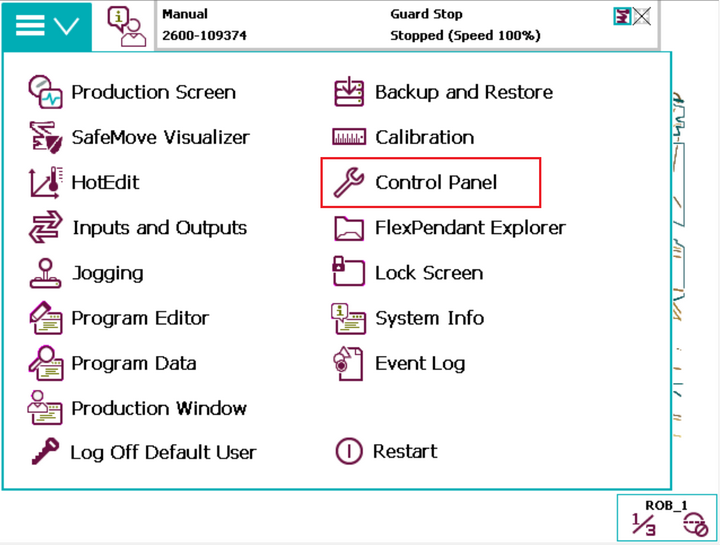
Turn on the IRC5 Controller, wait for Initialization Screen to appear, open Menu screen and select Control Panel option:
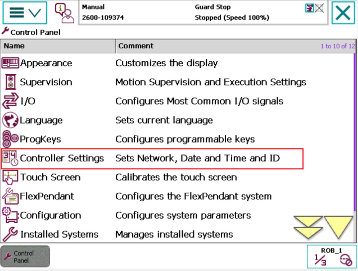
On the Control Panel pane, select Controller Settings:
Select Settings and choose Network option:
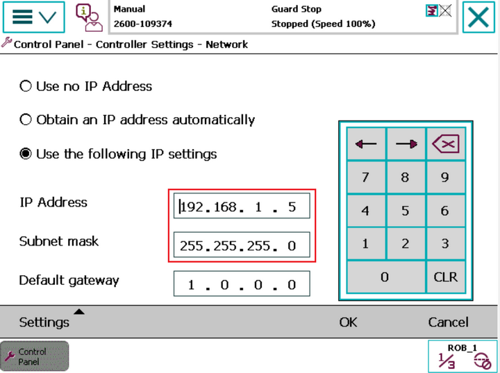
Network settings window should appear. Use the touch panel keypad to set an IP address of the IRC5 WAN port:
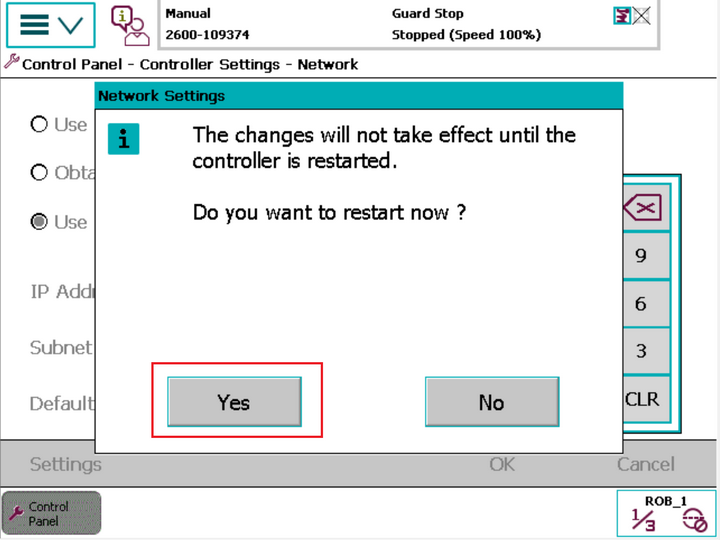
Press OK button and restart the controller to apply new settings:
3 Robot Studio Setup
3.1 Connect to IRC5 Controller from Robot Studio
Set your local PC network settings to DHCP, plug Ethernet cable to Service Port of IRC5 Controller and launch Robot Studio.
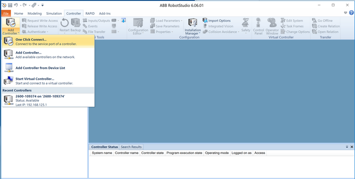
For direct connection to Robot Controller, select Controller tab and One Click Connect option:
3.2 Transfer RAPID files
As a first step in installation of Photoneo ABB Interface, you need to copy RAPID files from your PC to the Robot Controller
You can use USB stick and copy files directly via pendant, however the most convenient way is to use Robot Studio File Transfer tool.
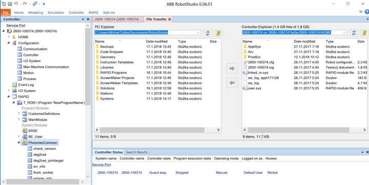
Go to Controller tab and select File Transfer tool from the menu:
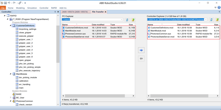
Photoneo ABB Interface consists of four RAPID files:
- MainModule.mod
- CustomerDefinitions.mod
- StateServer.mod
- PhotoneoCommon.sys
All these files need to be transferred to the HOME:/Photoneo/ folder created within the robot controller file system as shown by the figure below:
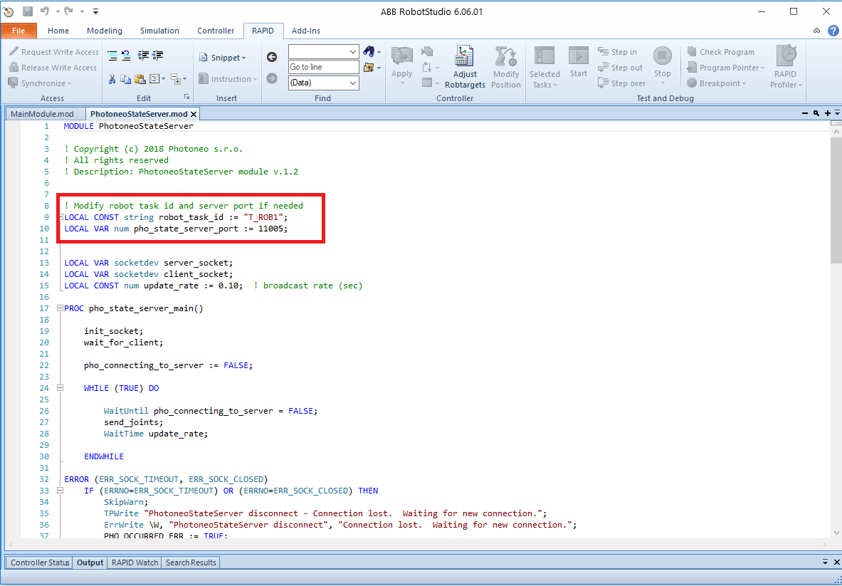
For correct functionality of State Server, please make sure that variables robot_task_id and pho_state_server_port are valid with respect to your system configuration.
(For example multi axes systems use T_ROB1 and T_ROB2 tasks, your network configuration might prevent using port 11005 etc). Keep default values if you are not confident about these changes.
3.3 Create State Server Task
As a next step we need to create State Server Task. State Server Task will run in background and will be used to report current robot state to the Vision Controller.
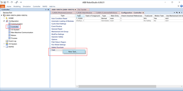
On the Left pane, click Controller then right click on the Task item in the list and select New Task...:
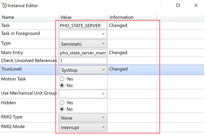
Following dialog should appear. Change settings as shown in the figure below:
3.4 Automatic Loading of Modules
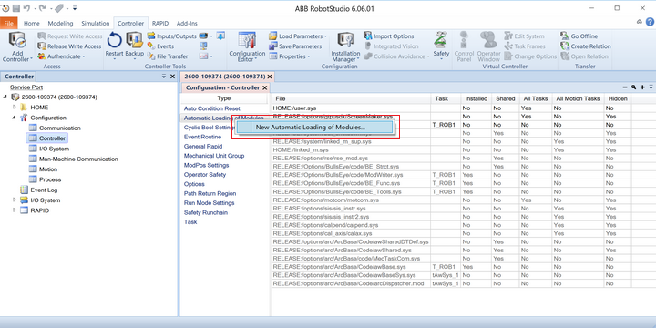
Now we need to configure ABB system to automatically load StateServer.mod during the boot. Right Click on Automatic Loading of Modules and Select New Automatic Loading of Modules as shown in the figure below:
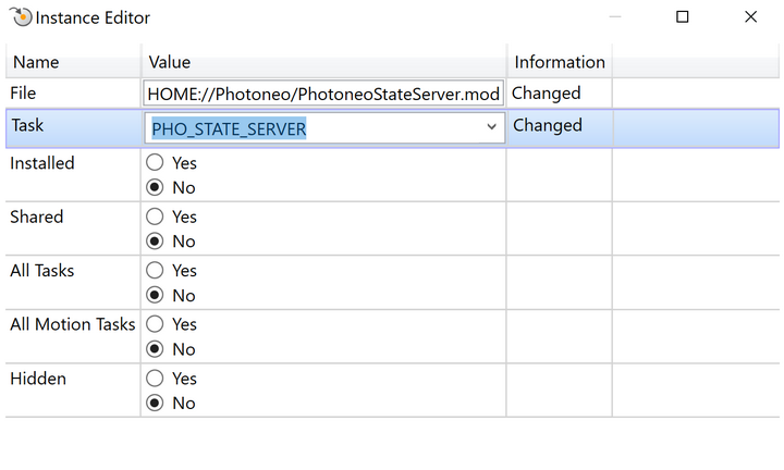
Configure module for State Server.mod as shown in the figure below:
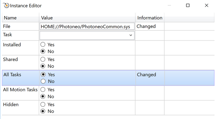
Repeat the same procedure for PhotoneoCommon.sys as a system module:
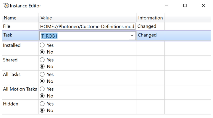
Repeat the same procedure also for CustomerDefinitions.mod containing user settings:
3.5 Load Main Module
Now we are ready to manually load MainModule.mod to T_ROB1 task. You can load the file from your PC or directly from the controller.
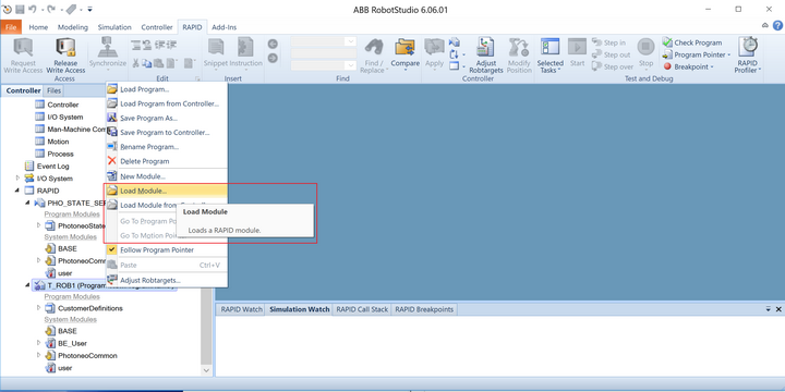
Right Click on T_ROB1 task and select Load Module or Load Module From Controller:
This was the last step installation step. Your RAPID pane should now look like this:
[[File:]]
4. RAPID
4.1 RAPID & Bin Picking Control
Following API described functionality of requests provided by Photoneo ABB Interface. They are intended for high level control of bin picking sequence and usually called in MainModule.mod.
pho_request_init(jointtarget pho_start_bin_picking_pose, jointtarget pho_end_bin_piking_pose) - request to initialize bin picking application on the Vision Controller side. Start and End Pose defined by the operator on the RAPID side are transferred to the Vision Controller and used in the trajectory planning pipeline as a start and terminus points.
pho_request_scan() - request to trigger next scan and localization. Non-blocking request, RAPID program continues immediately at the next line
pho_wait_for_scan_completition() - function to wait for scan to be finished. Must be called after triggering scan, but not immediately
pho_request_trajectory() - request to start trajectory planning for current goal. Non blocking function, RAPID program continues immediately at the next line
pho_receive_trajectory() - function to receive requested trajectory. This is usually called inside pho_bin_picking() function by default. Blocking function.
pho_request_scan_and_traj() - function to trigger scan, localization and trajectory planning in a single shot. Blocking function, handy for initial bin picking experiments. Dor real production it is more convenient to split this sequence into particular actions and call them accordingly.
pho_request_calib_add_point() - request to add calibration point - scan is triggered and calibration is recalculated. Blocking request, program does not continue until calibration result is recalculated and received by the robot controller.
pho_calib_set() - request to set current calibration result to the PhoXi Scanner
pho_calib_reset() - request to reset current calibration and remove all previously added points
pho_bin_picking() - request to execute bin picking operation. It usually receives requested trajectory and perform motion execution. Blocking function, program does not continue until the whole sequence is finished. Always make sure that robot is in pho_start_bin_picking_pose before calling this function.
=== 4.2 RAPID & Bin Picking Configuration
CustomerDefinitions.mod
PROC open_gripper() PROC close_gripper() PROC gripper_user_1() ....
PROC binpicking_settings() PROC pho_bin_picking_simple() PROC pho_bin_picking() PROC pho_execute_trajectory(num index, \speeddata speed, \zonedata zone) PROC execute_gripper(num index)
PhotoneoStateServer.mod
LOCAL CONST string robot_task_id := "T_ROB1"; LOCAL VAR num pho_state_server_port := 11005;
2.6 Configuring a I/O
2.6.1 Preparation
Assemble cables (tall box on palette with controller), specifically XP1, XP13, XP2 to the bottom side of controller, with their respective connectors on the base of robot.
2.6.2 Setting up I/O
Various links are accessible on panel inside cabinet. These signals are wired throught XS/XP13 connector underneath the cabinet, throught connection in base of robot to R1(2).CP and R1(2).CS. XT6/6.1 signals 1 to 4 are usually used to power your device (4x1mm2) with link to R1(2).CP and connectors XT5.1, XT5.2 and XT5.3 are used to provide signals for your accessories carried by robot with link to R1(2).CS.
2.3.3 Accessing signals in program
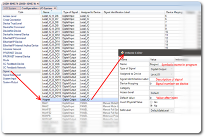
Usually a I/O slave is supplied with robotic controller. If not install one inside cabinet and in Configuration - I/O System tab. Once completed a list of device’s Inputs/Outputs may appear in Signals tab. Configure them according to their specific purpose. A example of signal configuration is shown below:
