PhoXi 3D scanners family
From 3D scanning Knowledge base - Photoneo wiki
This page contains technical description of PhoXi 3D Scanners. For scanning guide, see Scanning best practices.
Contents
General specification
| Light source | Visible red light (laser) |
| Wavelength | 638nm |
| Laser class | 3R (IEC / EN 60825-1, 2014) |
| Peak / CW Power | 314uW |
| Pulse Energy | 382nJ |
| Pulse Length | 960us |
| Projection angle horizontal | 47.5° ±1° |
| Projection angle vertical | 36.0° ±2° |
For model/size specific parameters see our product showcase.
Specification Parameters Explanation
- Depth Map resolution
- Maximum number of rendered points (the resolution of camera sensor)
- Point size
- The average distance between two neighboring points on the point cloud of a plane located in the focus distance of the camera. Alternatively, the square of the point size is the average surface sampled by one 3D point on the plane scanned in the focus distance of the camera.
- Calibration accuracy
- The accuracy of point measurement as the result of device calibration (can be understood as the space deformation). It is the standard deviation of the measurement error in the whole measurement range of the device.
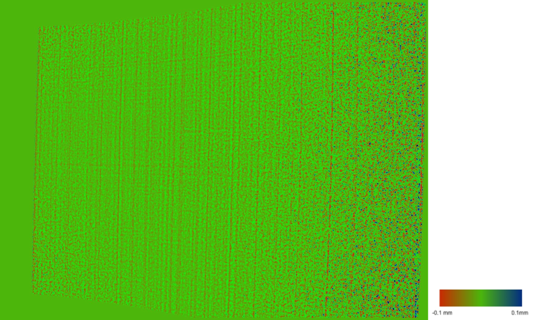
- Calibration accuracy is measured by scanning multiple planes at different distances from the scanner. Below you can see a scan of the plane done by the PhoXi 3D Scanner model S at the distance of 411mm. The red points are closer to the plane and the blue points are further away form the plane
- Calibration accuracy is the average distance of the 3D points from this plane.
- Temporal noise
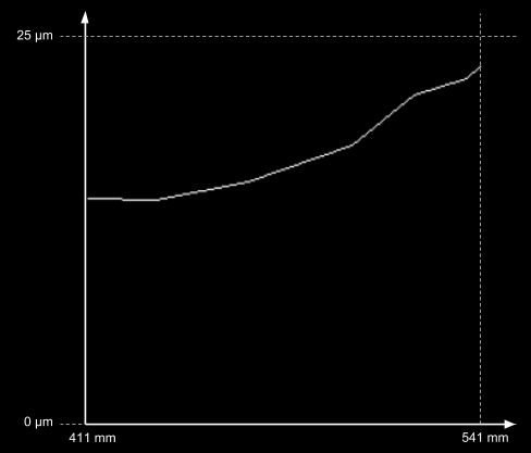
- The standard deviation of the noise (measured on a diffuse surface with 80 percent albedo). The noise level describes the quality of the sensor to capture local surface details. The noise distribution of our sensor is similar to the Gaussian distribution.
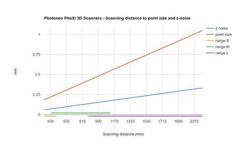
- Below is a graph depicting the Standard deviation of depth (Z-noise) values of 3D points for different scanning distances for the PhoXi 3D Scanner model S.
- Equivalently, Temporal noise can also be defined as the average distance of the 3D points from the average Z-value of the 3D points.
- FPS
- Maximum number of triggered frames per second, in fastest acquisition mode
- Data acquisition time - best case
- Fastest possible acquisition time
- Data acquisition time - worst case
- Longest expected acquisition time (bad lighting conditions, dark shiny objects)
- 3D points throughput
- Number of 3D points that can be reconstructed in a second in sequential scans
Connectivity
| Status LEDs meaning | |
|---|---|
| ⚫ Power status
Power cable connected |
⚫ Processing unit connected On => Suitable power connected |
| ⚫ Reserved
- |
⚫ Reserved
- |
| ⚫ Ethernet speed Off => Indicates 1 Gbps |
⚫ Ethernet activity Off => Link is down |
Pinout
Power + GPIO Pinout
Power + GPIO port:
- Use 12 VDC to power the scanner.
- Use only the supplied power adapter.
- The I/O ports are reserved for future use.
| View from the mating side |
| Pin # | Pinout | Note |
|---|---|---|
| 1 | IN2 | Opto-isolated |
| 2 | IN1 | Opto-isolated |
| 3 | OUT2 | Opto-isolated |
| 4 | OUT1 | Opto-isolated |
| 5 | POWER_+12VDC | N/A |
| 6 | POWER_GND | N/A |
| 7 | GPIO1 | Non-isolated |
| 8 | GPIO3 | Non-isolated |
| 9 | GPIO2 | Non-isolated |
| 10 | IN_GND | N/A |
| 11 | OUT_GND | N/A |
| 12 | GPIO4 | Non-isolated |
Ethernet Pinout
Ethernet port:
- Powering the device through the ethernet port (PoE) is not possible.
- Connect 1 Gbps ethernet adapter with RJ45 socket (supplied with scanner).
- Use category Cat5e or better ethernet cables (cables capable of 1 Gbps or 10 Gbps transfer rate).
| View from the mating side |
| Pin # | Cable Color | Pinout |
|---|---|---|
| 1 | White green | MD1_P |
| 2 | (+) Red | 12V_IN |
| 3 | White blue | MD2_N |
| 4 | Blue | MD2_P |
| 5 | White orange | MD0_P |
| 6 | Orange | MD0_N |
| 7 | White brown | MD3_P |
| 8 | (-) Black | GND |
| 9 | Green | MD1_N |
| 10 | Brown | MD3_N |
Please contact support@photoneo.com for specific explanation regarding pin outs.
CAD data
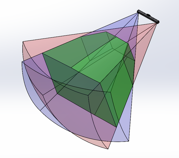
Contains 3D Scanner body and its scanning volume as a solid object.
Available CAD models for download:
| Device | Mounting space coordinate space | Camera coordinate space |
|---|---|---|
| PhoXi 3D Scanner XS | XS - mounting space | XS - camera space |
| PhoXi 3D Scanner S | S - mounting space | S - camera space |
| PhoXi 3D Scanner M | M - mounting space | M - camera space |
| PhoXi 3D Scanner L | L - mounting space | L - camera space |
| PhoXi 3D Scanner XL | XL - mounting space | XL - camera space |
| All in mounting space | All in camera space |
Note: Camera coordinate space is only approximate.
