Frequently asked questions and Frequently experienced difficulties
Software download: Downloads and information
Contents
- 1 FAQ
- 1.1 How do I save the point cloud?
- 1.2 How do I retrieve the intrinsic parameters of the scanner?
- 1.3 How do I set a static IP address for a Photoneo PhoXi 3D Scanner with firmware v1.1.x on Ubuntu 16.04 systems?
- 1.4 How do I scan reflective materials?
- 1.5 How do I change settings of the scanner using API?
- 1.6 The resulting point cloud contains artefacts
- 1.7 Is it possible to get a RGB pointcloud instead of a Grey-scale pointcloud?
- 2 FED
- 3 Upgrading firmware on your scanner
- 4 Connecting multiple scanners to one computer
- 5 Make PhoXi Control automatically connect to a specific scanner
- 6 Guide to building SimpleLocateExample using Localization SDK
- 7 The Depthmap has not transformed with a modification of the coordinate system of the scan
FAQ
How do I save the point cloud?
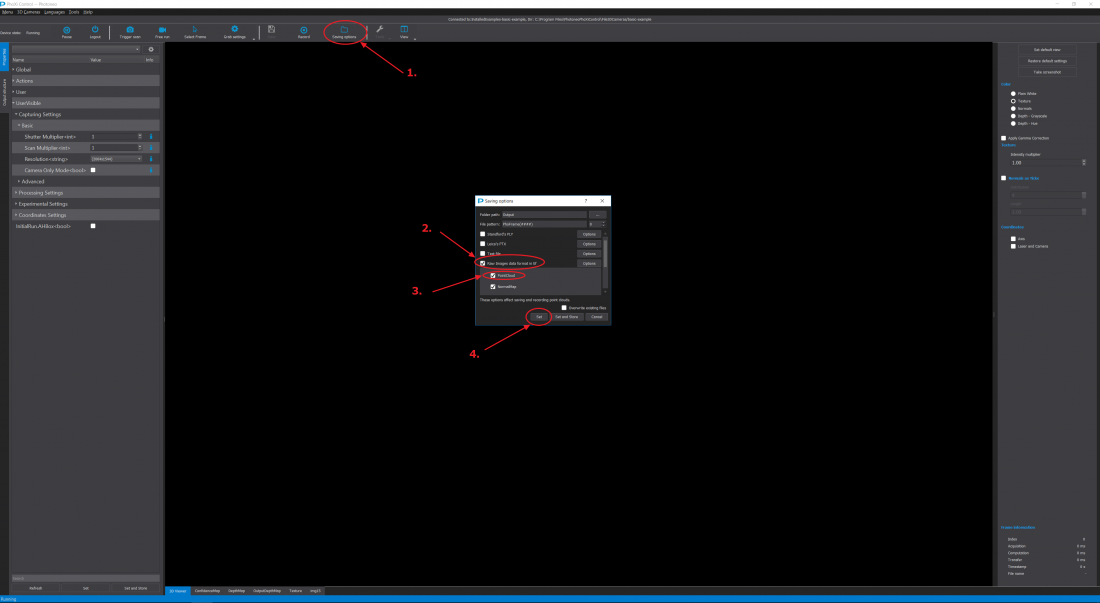
To save the current point cloud, use the button "SavePointCloud" in the top panel. The file will be stored in selected file format. To choose what data will be stored in the file, click "Recording options" button and then button "Options" next to the desired file format.
Most general file format is PLY. Useful data to save are PointCloud, NormalMap, Texture and use BinaryFormat.
When you want to save all information about the scan, use Photoneo's Raw data format.
To automatically store every captured frame, use the "Record" button. Point clouds will be saved in the directory and file formats set in "Recording Options".
How do I retrieve the intrinsic parameters of the scanner?
Download the following zip file for Windows here.
Download the following zip file for Ubuntu here.
Extract the zip file and follow the README.txt file.
All of the coefficients are compatible with the OpenCV standard, you can read about the OpenCV standard here
How do I set a static IP address for a Photoneo PhoXi 3D Scanner with firmware v1.1.x on Ubuntu 16.04 systems?
If you need to set the IP address for a scanner with firmware v1.1.x and all you have is a Ubuntu PC (16.04) with avahi-tools installed you can do so using the phoxi_3d_scanner_set_ip.sh script. The script works also on the scanner itself.
To set static IP address use it like this:
./phoxi_3d_scanner_set_ip.sh 2018-08-011-LC3 1 10.0.0.10 10.0.0.1 255.255.255.0 10.0.0.1
If you want to set dynamic address:
./phoxi_3d_scanner_set_ip.sh 2018-08-011-LC3 1 dhcp
The second parameter, CHANGE_REQUEST_ID, is a sequential integer number that needs to be incremented with each subsequent change. To find out what is the current value use the avahi-browse tool, for example:
$ avahi-browse -r -t _3d-camera._tcp
The terminal will show the following output:
+ enp0s31f6 IPv4 PhoXi3DScan-2018-08-011-LC3                   _3d-camera._tcp      local

= enp0s31f6 IPv4 PhoXi3DScan-2018-08-011-LC3                   _3d-camera._tcp      local

  hostname = [ytrium1.local]

  address = [10.0.0.10]

  port = [65499]

  txt = ["Occupied_By: ::ffff:10.0.0.1" "changeId: 2" "version: 1.1.62" "status: Occupied" "description: Photoneo 3D Scanner" "id: 2018-08-011-LC3"]
So in this case we would use value 3 in next change IP request.
How do I scan reflective materials?
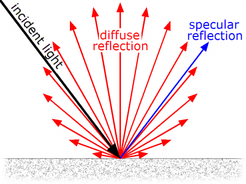
PhoXi 3D scanner uses diffuse reflection of the projected 3D pattern to reconstruct the surface of objects.
The following scheme depicts the difference between a beam reflected diffusely and specularly.
(source: Wikipedia )
In general, there are two main reasons for lower quality 3D reconstruction of reflective surfaces:
1) Reflective materials prevent diffuse reflection, this causes the projected laser pattern to have lower contrast between the dark and light stripes.
2) Interference, the specularly reflected laser pattern interferes with the diffusely reflected laser pattern and leads to incorrect pattern perception.
The following can be done to increase the quality:
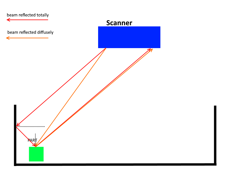
1) Try changing the scanning angle, if the scanner is scanning the object from the side move it so that it is directly above the scanned object. This will cause more beams that are totally reflected to not be reflected back to the camera unit and therefore, not interfere with the diffusely reflected laser pattern. In general, the best method to get the best scan through trial and error and finding the optimal scanning position.
2) If sides the bin in which the object is inside of is reflective, then this utility can be used. (Please follow the README.txt, incorrect use of this utility can cause your scanner to be improperly calibrated) It will narrow the range of the projected laser pattern and therefore the red beam shown in the picture below will not be projected.
How do I change settings of the scanner using API?
From PhoXi API v1.2.X and with Firmware v1.2.X it is possible to change scanning parameters using the API. The modified FullAPIExample that shows how this is done can be found here.
The resulting point cloud contains artefacts
To remove noise artefacts from the scene, it is recommended using this (Ubuntu this) utility, which to turns on the guided filter. You can read about the guided filter here . For more advanced users, you can also modify the input values for the guided filter and also the bilateral filter. You can download the advanced utility here (Ubuntu here). You can read about the bilateral filter here.
Is it possible to get a RGB pointcloud instead of a Grey-scale pointcloud?
There are two ways of creating a colored pointcloud using a PhoXi 3D scanner.
- 1) Using an external color camera
There is a possibility of using an external color camera, we would recommend placing this camera right below or above the scanner. However, the image made by this camera has to be integrated into the final pointcloud. This can be done via a mathematical computation using the intrinsic parameters of this colored camera.
- 2) Production of a customized scanner
The customized scanner would contain two cameras in its camera unit and the second one would take a colored image of the scene integrated into the final pointcloud
If a customer is interested in any of these options, both of them will have to be discussed internally at Photoneo. Whether Photoneo will be able to calibrate an external color camera (option (1)) or produce a customized scanner (option (2)) for the customer will depend on his/hers specific application and on the potentiality of collaboration between Photoneo and the customer. This is handled by the Sales department of Photoneo and can be contacted at sales@photoneo.com.
FED
Corrupted Image Error
If during your scanning you are not able to get scans because "Image was corrupted" error, in most cases, this is caused when the coordinate space is set to markerspace and recognize markers is turned on, even though there is no marker pattern in the scene.
Be sure that you have set these settings.
Also, the second most common cause, is due to slow ethernet connection. The scanner requires a 1Gbit/s connection.
You can test your connection speed in PhoXi Control v1.2.X.
With 1Gbit connection your speed should be around 100MB/s.
Upgrading firmware on your scanner
This method only works with PhoXiControl release candidate v1.2.3 or higher and with scanner firmware v1.2.1 or higher. DO NOT USE THIS GUIDE, if your firmware version is lower than v1.2.1 (If you would like to upgrade firmware lower than v1.2.1 contact us at support@photoneo.com)
- 1) Contact us at support@photoneo.com and we will provide you with a .deb file, this is the installer for the firmware.
- 2) Open PhoXiControl and connect to the scanner you want upgrade your firmware on.
- 3) Click on the tools pane at the middle of the toolbar (it is represented by a wrench icon)
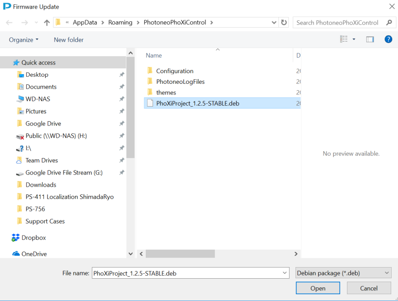
- 4) The following window will open, find the .deb file on your computer, then click open.
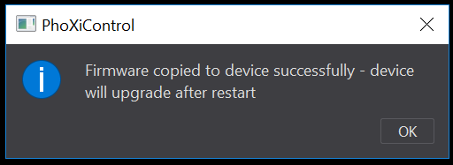
- 5) The cofirmation window will pop-up and your scanner will restart and upgrade.
Connecting multiple scanners to one computer
- Using PhoXi Control
In PhoXi Control it is possible to connect to two scanners at the same time and trigger the scans one after another.
Connect to the first scanner, then click menu -> network discovery and then click the second scanner you want to connect to.
You will then have two tabs as you can see in the picture below and then you can change between the two tabs by clicking on them.

- Using the PhoXi API
Connecting mutliple scanners can also be done using the PhoXi API, you can download the example code for this here.
Important points to note are: 1) Define SCANNER_HWID_1 and SCANNER_HWID_2 to the correct Hardware identification strings of your scanners
2) Do not attempt to create 2 instances of pho::api::PhoXiFactory, instead create just 1 factory and call CreateAndConnect method twice to get 2 pointers to different scanners
Make PhoXi Control automatically connect to a specific scanner
You can download this utility, which will allow you to run PhoXi Control and automatically connect to one specific scanner. Please follow the readme.txt. The utility uses the PhoXi API and the source is included in the .zip file.
Guide to building SimpleLocateExample using Localization SDK
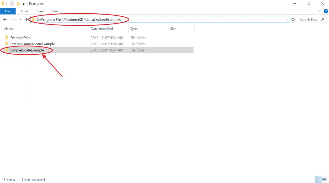
1) Find the SimpleLocateExample folder (by default in C:\Program Files\PhotoneoSDK\Localization\Examples\)
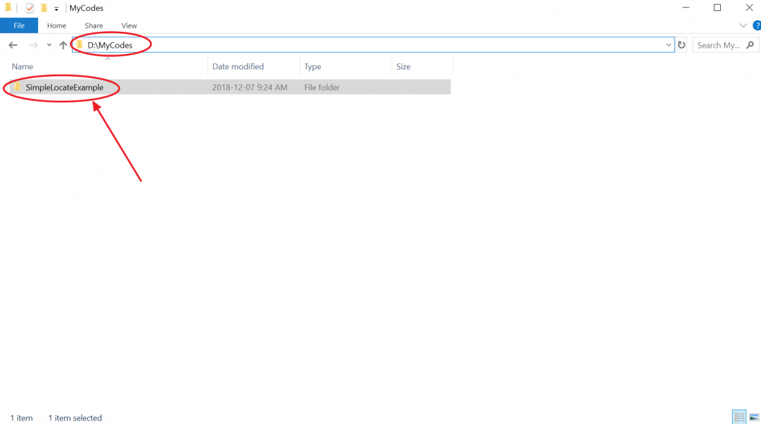
2) Copy this folder to a separate directory
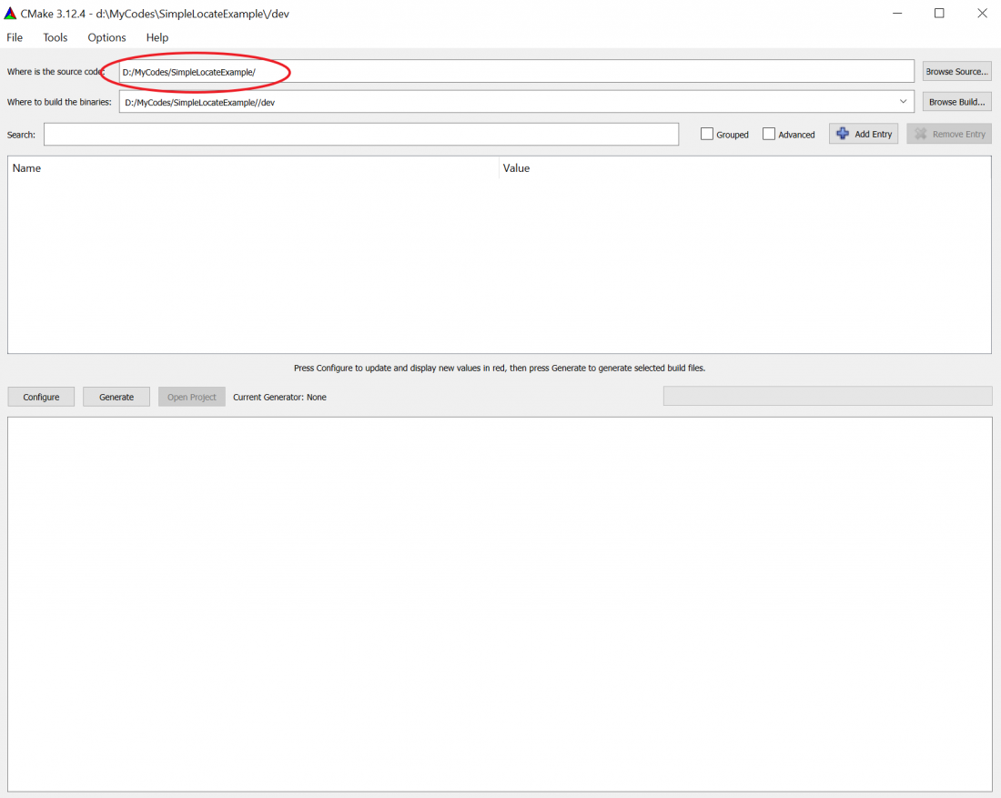
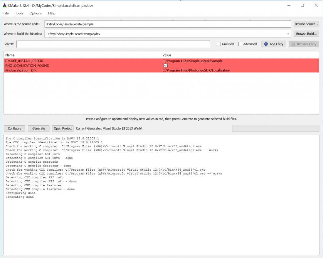
3) Open Cmake (you can download it here), input the source code path and where the binaries should be built (Photoneo recommends creating a /dev folder in the same path as the source code path)
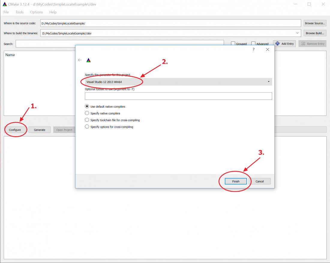
4) Do the instructions based on the image, make you use Visual Studio 12 2013 Win64 generator, DO NOT USE A DIFFERENT GENERATOR, your program will NOT work. You will able to run the solution with VS 2013, VS 2015, VS 2017.
footnote: If you get an error "Failed to run MSBuild command: MSBuild.exe." Then Photoneo recommends installing Visual Studio Express 2013 for Windows Desktop, the newer licences are applicable for this software.
5) Click the Generate button, this is how the window should look
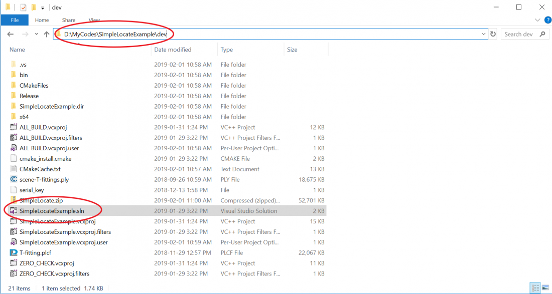
6) Go to /dev folder and find the .sln file, this file can be opened with VS 2013, VS 2015, VS 2017.
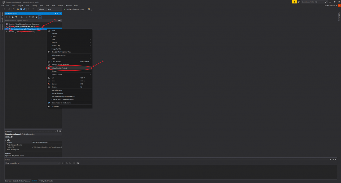
7) When you open the file in VS right-click SimpleLocateExample (Visual Studio 2013) on the Solution Explorer Pane and Set it as a startup project.
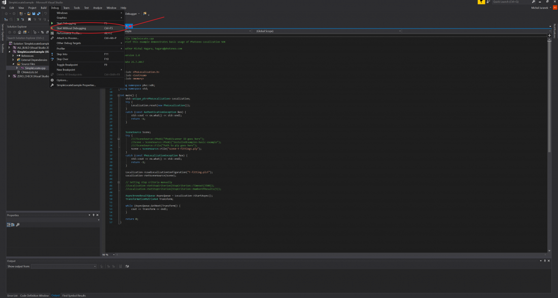
8) Finally, run the code
The Depthmap has not transformed with a modification of the coordinate system of the scan
The Depthmap, by definition, is an image containing Z-values of the default coordinate system (camera coordinate system).
The get the "transformed" depthmap (i.e. Z-values of the custom coordinate system), Photoneo recommends the following:
1) To be Continued
