Locator Tutorial: Setting up Locator to work with UR robots
Users are strongly recommended to read Locator Tutorial: Introduction prior to installation of specific robot interfaces
Contents
1. Prerequisites
Prior to setup, please ensure that your UR controller meets the following criteria:
- CB3.1 or E-series Controller
- System version 3.2 and higher
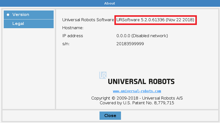
Click Menu -> About to verify your controller System Version (see figure below):
2. UR Controller Setup
2.1 Set IP Address of Ethernet Port
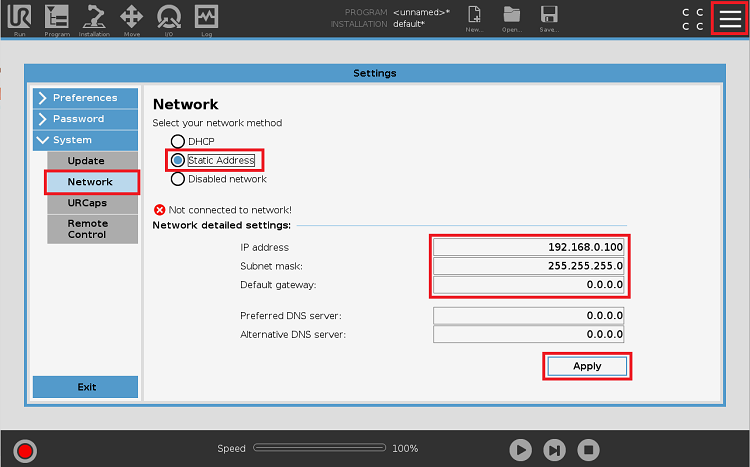
The first step of the process is to configure the IP address of the Robot Controller. Using the Teach Pendant, browse to Menu -> System -> Network:
Amend the IP Address and Subnet Mask to match the network configuration of the Vision Controller running Locator and click Apply:
3. Locator UR Cap Setup
The Locator UR Interface is distributed as a URCap and as simple URScript program template. The first step of the process is the installation of URCap.
Extract the Locator URCap archive (.zip file) to the USB stick and plug it into the Teach Pendant.
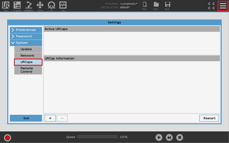
Browse to Menu -> System -> URCaps:
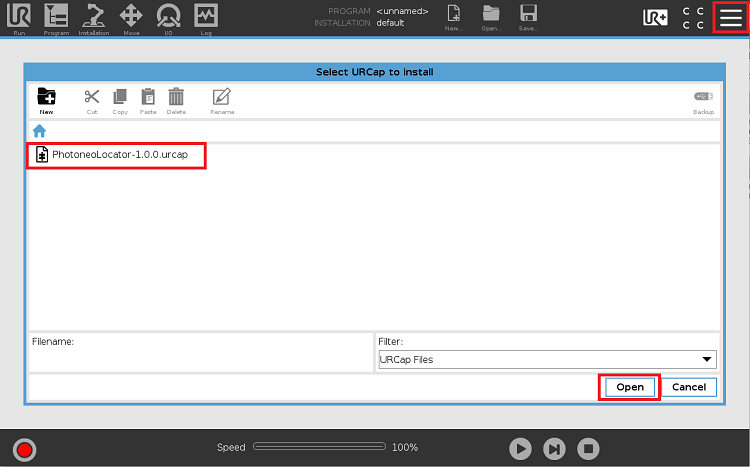
Select the PhotoneoLocator URCap file from the USB and click Open:
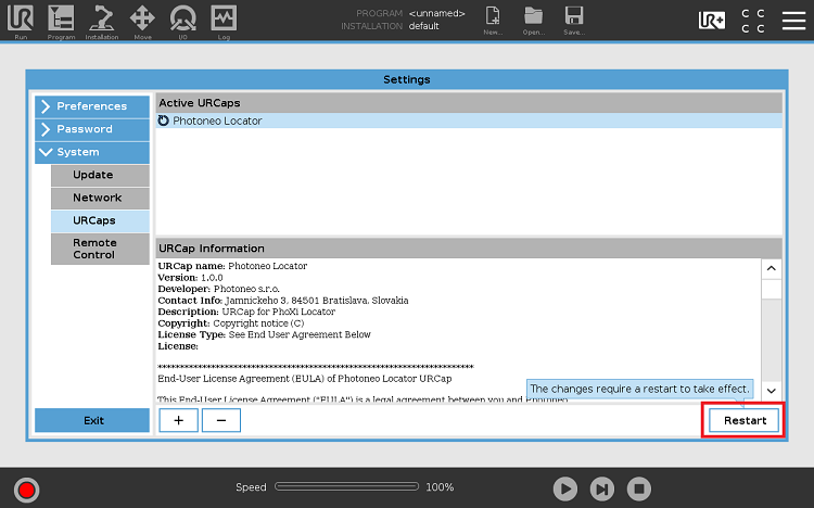
Locator URCap should now appear in the list of active URCaps. As always, a Restart is needed in order to enable the full functionality of the newly installed URCap.
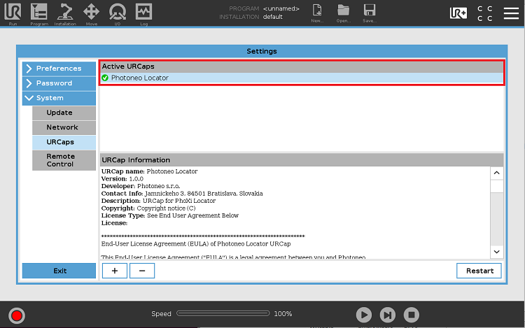
After the restart, Locator URCap should be ready for use:
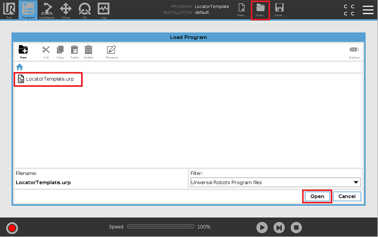
As a final step before Calibration, copy the LocatorTemplate.urp program from the USB to the Robot Controller:
NOTE: The configuration of LocatorTemplate will be explained in detail in Section 5.
4. Calibration
Robot Camera Calibration is a crucial step in Locator configuration. Accurate calibration ensures that object positions will be calculated directly in Robot Base coordinates.
Photoneo Robot Camera Calibration for URCap is configured to search for a spherical object, with a pre-determined radius. Ping-Pong or Snooker balls are typically used for this purpose. The Spherical object can be attached to the gripper using a peg, a suction cup two-finger gripper or another method. The pose of the ping pong ball is not important (it doesn't need to be in axis); the only requirement is that it should be mounted firmly to ensure that it remains stationary during transitions between waypoints. It should also be visible from the Scanner at each waypoint.
NOTE: Tool Point setting does not affect the calibration process and it is, therefore, not necessary to clear tool pose configuration before starting the calibration.
4.1 Robot - Camera Calibration
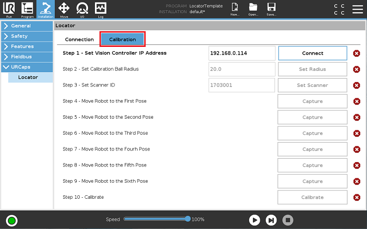
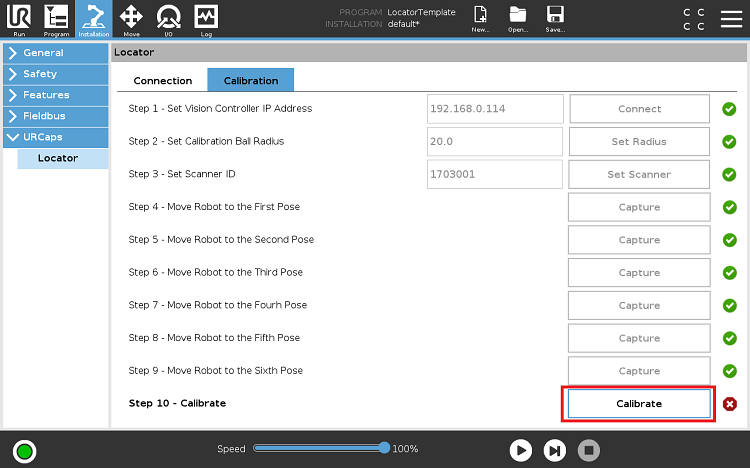
Mount the Scanner firmly, ensure that the scene is properly captured from the final Scanner position and open the Calibration tab on the Installation page:
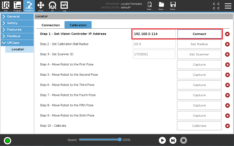
As a first step, set the IP address of the Vision Controller and press the Connect button to establish a connection to the Calibration Tool:
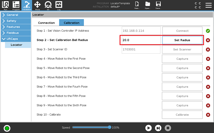
Next, insert and set the Sphere radius (Standard Ping Pong Ball = 20mm, Snooker Ball = 26.25mm):
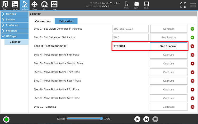
The third step requires Scanner ID to be set. Both old & new notations are supported. (Old notation example: 1703001 / New notation example: 2018-03-001-LC3)
NOTE: If you have inserted an incorrect value and need to restart the calibration process, just switch from the Installation Tab to the Program Tab and back. Calibration will be restarted.
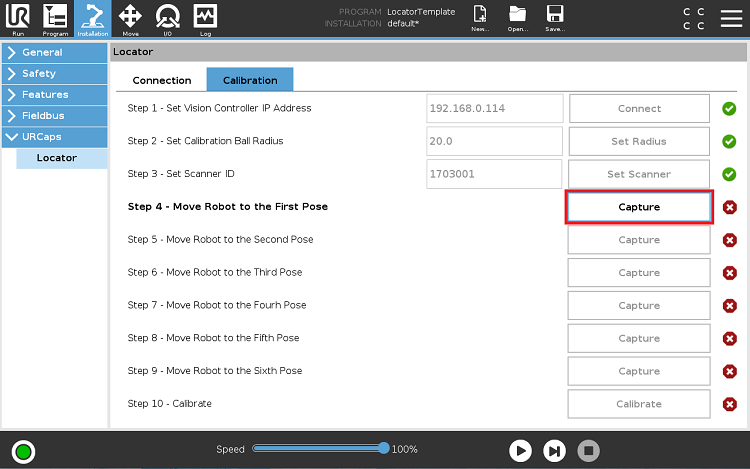
You are now ready to start adding calibration points. Hold the Enable button and manually move the robot to the first calibration pose.
The recommended procedure is to cover all four corners of the scanning volume/bin + two positions in the center of the scanning volume.
Press the Capture button to trigger the scan and store the current calibration position. Repeat the same procedure for all 6 calibration points:
NOTE: If the calibration ball has not been detected properly, a popup window notifies the user that the calibration point needs to be changed and recaptured!
Once all 6 points have been added successfully, it is time to calculate the calibration matrix and store the results to the Scanner. Press Calibrate to finalize the calibration procedure:
NOTE: If the calibration error is too high, the entire calibration process should be repeated with calibration with different calibration waypoints!
4.2 Tool Configuration
After finalizing Robot Camera calibration the Tool Point should be configured.
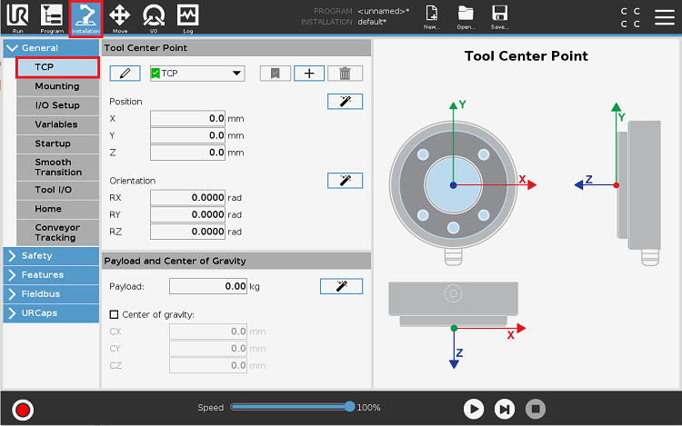
Browse to Menu -> Setup -> Frames and select the tool frame you want to use within your program.
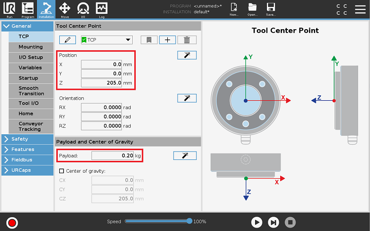
Set the X,Y,Z coordinates which denote the position of the tool point of the current gripper with respect to the flange:
Tool Configuration must be performed before reteaching application poses!
5. Runtime
5.1 Reteach Application poses
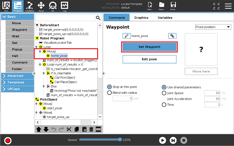
Once the Robot-Camera and Tool calibration processes have been completed, application poses must be retaught. Prior to starting this process, please ensure that you have selected the correct Tool Frame.
Go through the LocatorTemplate program and reteach Home Start, End + Placing positions using the standard procedure as shown in the figure below:
5.2 Remaining Locator Configuration
Locator configuration on UR side comprises few more options. First of them is related to the gripper logic.
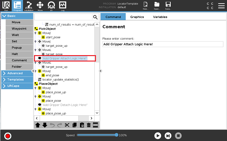
Replace the following comments in the UR Script code with specific commands for attaching the object to the gripper:
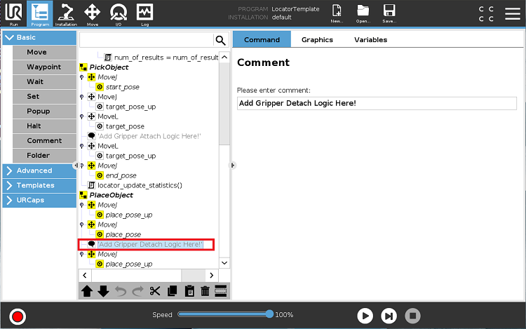
Repeat the same step with the Gripper Detach command:
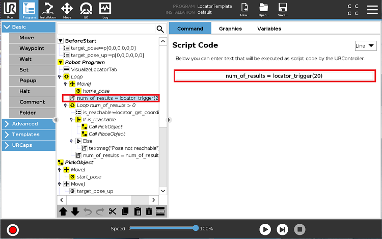
Locator for URCap always works in Multiple Result Mode - the user specifies how many results should be retrieved from a single scan. This is implemented through the parameter in the locator_trigger function call e.g. locator_trigger(20). This configuration is closely coupled to the Stop Criteria settings of the Photoneo Localization Configuration File (PLCF) on the Locator side.
EXAMPLE: The only enabled Stop Criteria is "Total time is configured to 20000ms". Let's assume that Localization has found 32 objects during this period. Locator Best Result Selector is set to Max X criteria. Locator receives 32 results from the localization, sorts them according to the X coordinates and transmits the 20 top results to the URCap. URCap receives these 20 results and starts picking the objects one by one. If only 15 objects are found by the localization, Locator transmits all 15 sorted results to the URCap.
During locator_trigger execution, all results are received by the internal Locator URCap buffer. Following function call - locator_get_coordinates retrieves values from this buffer and attempts to execute picks one by one.
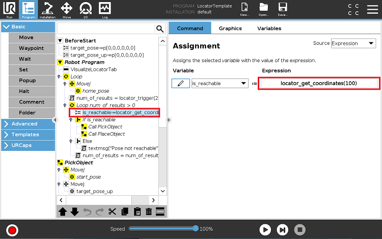
In order to ensure optimal picking, it is recommended to approach the object linearly on the Z-axis. The parameter in locator_get_coordinates(z_axis_offset) sets the approaching height on the Z-axis (Unit = millimeters).
During locator_get_coordinates execution, the next Cartesian Coordinates are retrieved from the buffer and stored to the target_pose variable. The target_pose_up is calculated as a simple sum of target_pose and Z-axis offset. If both poses are kinematically reachable, the actual pick begins; if not, the next Cartesian Result is processed.
5.3 Run Locator
You are now ready to run the program. Select 10% speed; this option is recommended for safety reasons.
Ensure that you are ready to stop the motion execution immediately if something goes wrong.
If everything is working correctly, you should see that the scan has been triggered, the result from Locator has been transmitted to the Robot Controller and the robot is approaching the first object.
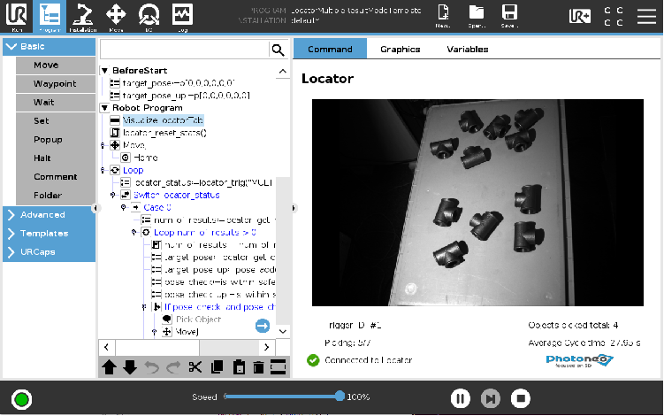
The VisualizeLocatorTab line of code shows the Texture from the Scanner and picking statistics such as the number of scans triggered, the total number of picks, and the average cycle time.
6. UR Script
Locator URCap utilizes Python Daemon which runs in the background and handles communication with Locator. This approach enables the simplification of Locator API to only three URScript functions.
6.1 Main
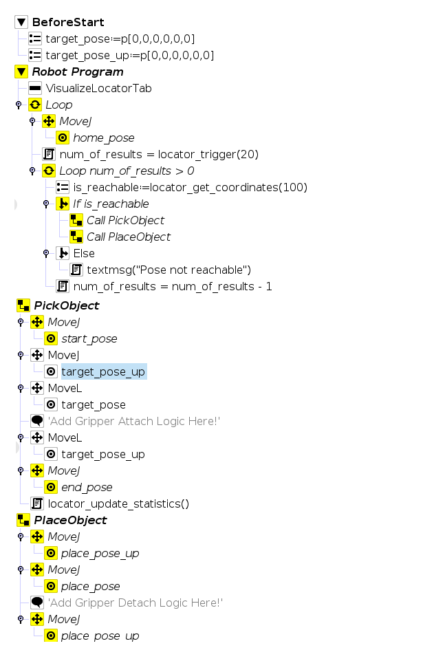
The following figure describes the LocatorTemplate.upr program. As can be seen, 20 results are requested and the approaching height to each of the objects is set to 100mm.
If at least one object pose is received, the program will attempt to execute motion towards the returned target/s. The attached object/s will be then placed in predefined positions.
Users can adapt this URScript code to meet their application requirements; amend the speed, blend or logic if needed.
6.2 UR Script API
Locator URScript API is comprised of three functions which provide a high-level interface to Locator:
- - locator_trigger(num_of_results) - this function triggers the scan and starts localization. Input Argument: Number of Requested Results. Return Value: Num of Localized Objects
- - locator_get_coordinates(z_axis_offset) - this function fetches the next coordinate from the result buffer and validates the reachability for both approaching and grasping poses. Input Argument: Z-Axis Approaching Offset, Return Value: Reachable - True/False
- - locator_update_statistics() - this function updates picking statistics at the visualization pane after each pick. Input Argument: None, Return Value: None
6.3 Communication Protocol
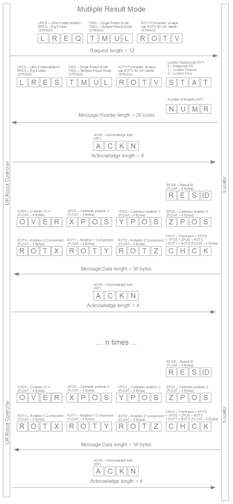
The following illustrations describe the Locator - UR communication protocol. As has already been mentioned, Locator URCap always works in Multiple Result Mode.
The current implementation prevents the user from programming communication routines which are handled entirely by the Python Daemon.
