Binpicking Tutorial: Setting up Photoneo BP Studio with KUKA IIWA
Contents
1. Prerequisites
No special prerequisites are known by the time of writing this tutorial.
2. KUKA Controller setup
This tutorial was written using Sunrise Workbench v.1.11, however it should be compatible with different version with minor changes.
2.1 KONI Interface Setup
KUKA IIWA controller has sever Ethernet ports. In order to enable communication with Vision Controller we are going to make use of KONI port.
KONI interface by default belongs to Real Time KUKA OS and is available only for FRI. Make sure that assigning KONI interface to Windows will not break anything important at the customer.
If customer approve this change, follow steps below to assign KONI interface to Windows:
1. Log into the cabinet
Use DVI port + Keyboard + Mouse for direct access to Windows 7 Embedded as KukaUser.
The Windows 7 Embedded should start up with KukaUser already logged in, use following credentials if you have any problems: Login: administrator Password: 68kuka1secpw59
2. Shutdown KRC
Right click on the green icon in the system tray (bottom right, next to clock) and click Stop KRC.
3. Check the network interfaces
Open the list of the network interfaces: Start -> View newtwork connections
At this point you should only have one interface: Realtime OS Virtual Network Adapter - DO NOT EVER CHANGE THIS SETTINGS!
4. Open terminal and type
C:\KUKA\Hardware\Manager\KUKAHardwareManager.exe -assign OptionNIC -os WIN
This will assign the KONI interface to Windows.
5. Change KONI IP settings
Reboot and open Start -> View network connections again.
Change the settings (IP address) of the new Ethernet adapter to the one you want to use - within the Network adapter settings in Windows, for example, 160.69.69.69 is recommended.
NOTE: To revert changes type: C:\KUKA\Hardware\Manager\KUKAHardwareManager.exe -assign OptionNIC -os RTOS
2.2 Create new sunrise project
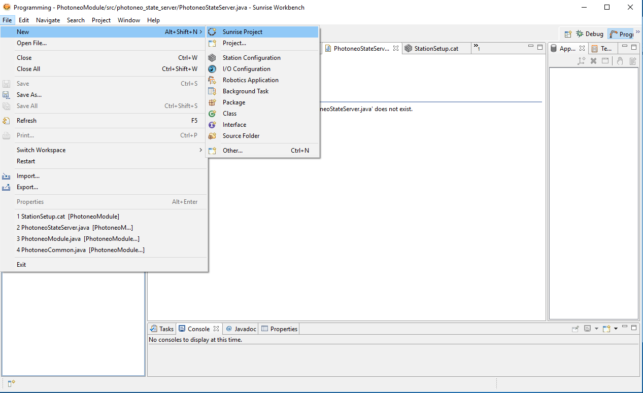
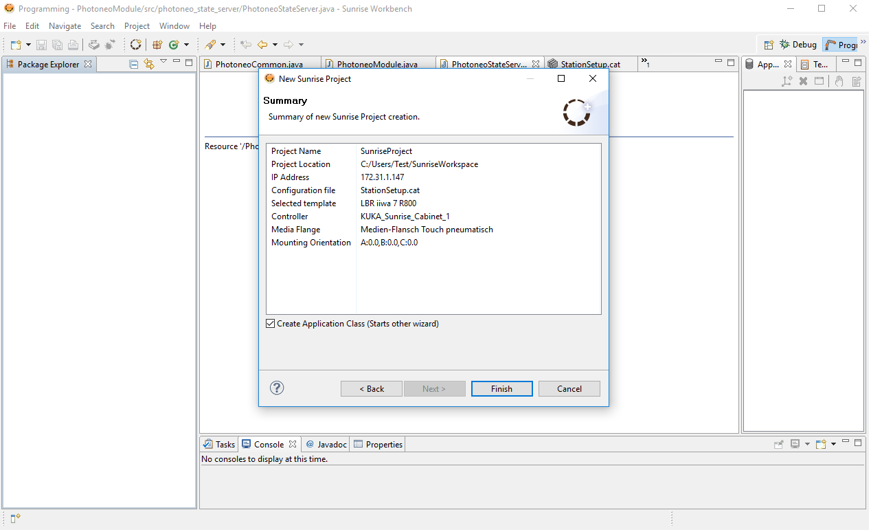
Start by creating new Sunrise Project. Select New -> Sunrise Project
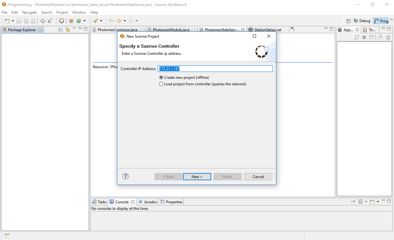
Make sure that IP Address of KUKA Controller is configured properly:
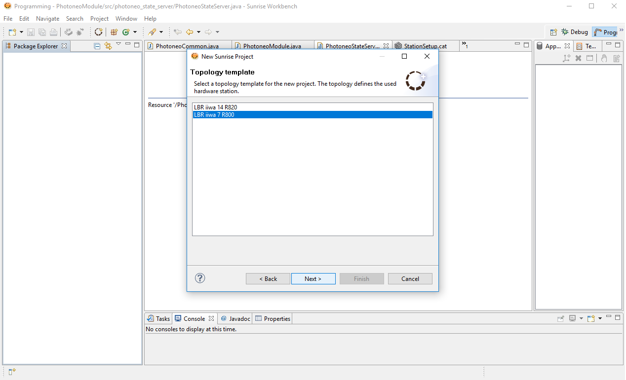
Select which version of manipulator you use, KUKA IIWA 7 R800 was used in this tutorial:
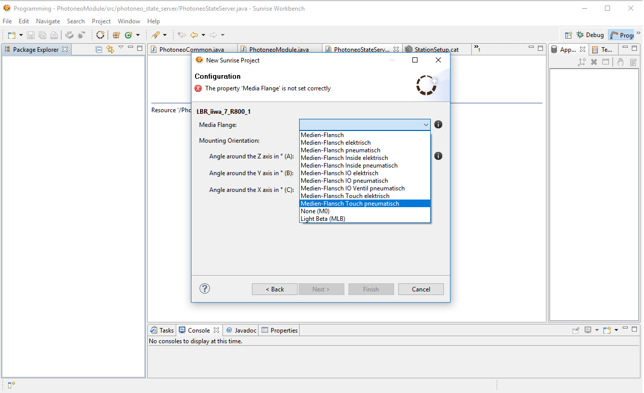
Select flange type, Medien Flanch Touch Pneumatisch was use in this tutorial:
Review Summary of Sunrise Project and click Finish Button.
2.3 Project Configuration
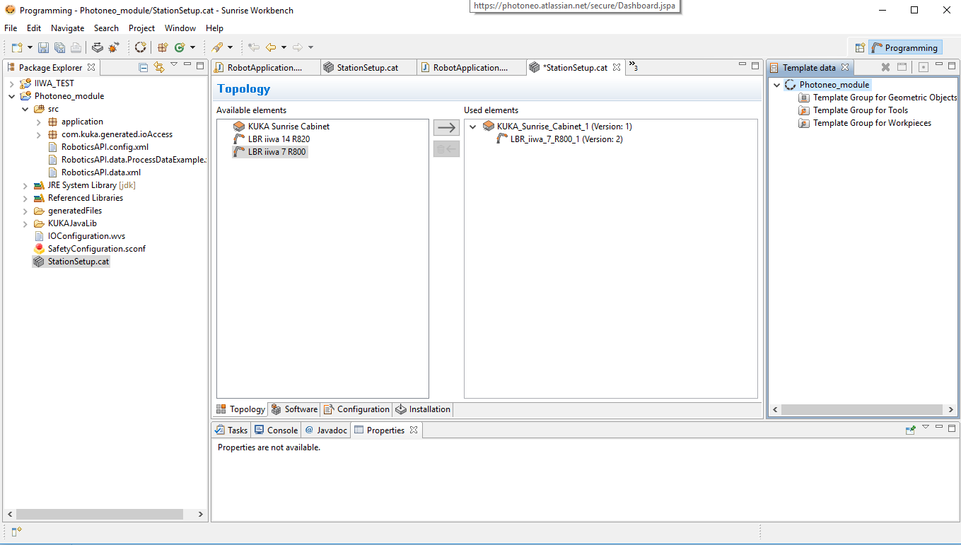
Enter StationSetup.cat option in Project Overview
On Topology Tab add your version of KUKA IIWA to the robot to the Used Element under KUKA Sunrise Cabinet:
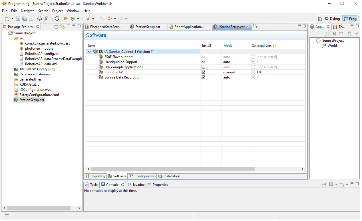
On the Software tab make sure that all important software components are included in installation, especially Robotics API:
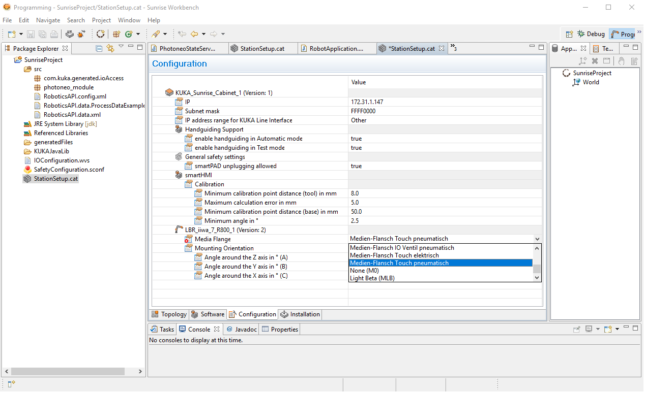
On the Configuration Tab select flange type again:
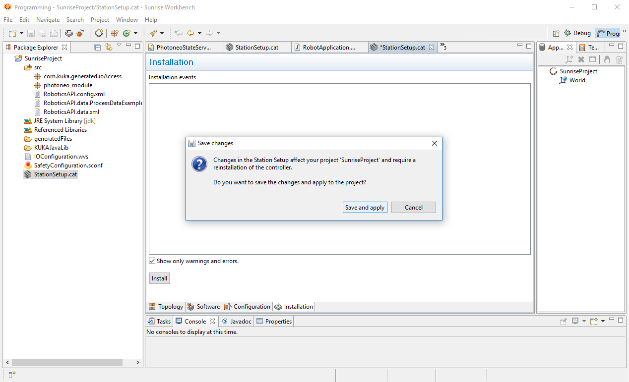
Proceed to Installation Tab and Install the project to the controller, click Save and Apply:
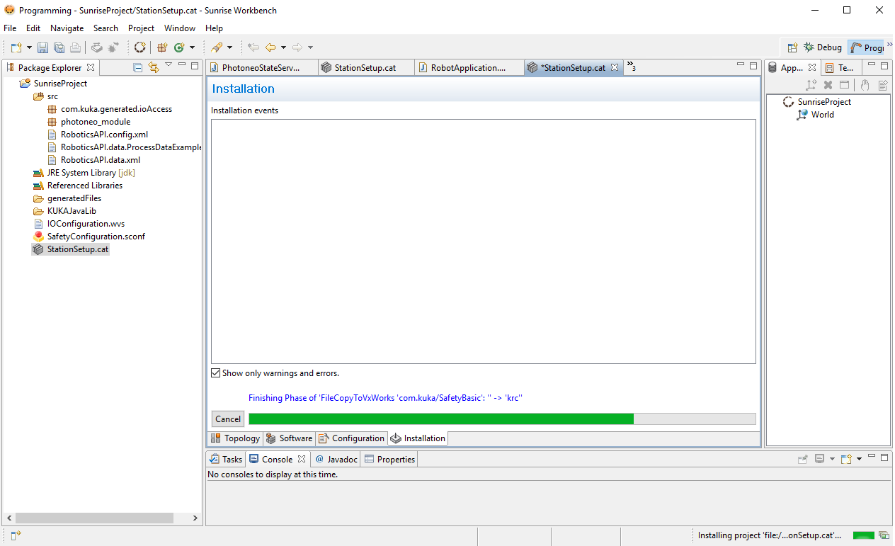
Project files should be copied to the robot controller now:
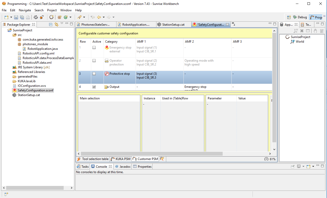
OPTIONAL: If you do not use safety PLC and need to disable safety features open SafetyConfiguration.cat file and disable first three rows (Emergency Stop External, Operator protection and Protective Setup).
Safety Settings will be applied during project synchronization later.
2.4 Installation of Photoneo Module
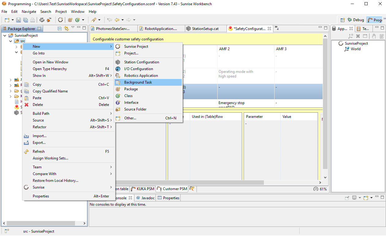
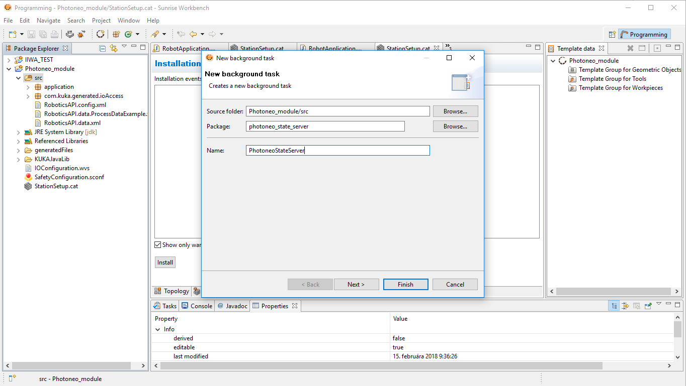
Photoneo KUKA IIWA Module consists of two tasks - State Server and Client. First we configure Background task for State Server. Right Click on src -> New -> Background Task.
Enter following names: Package: photoneo_state_server, Name: PhotoneoStateServer
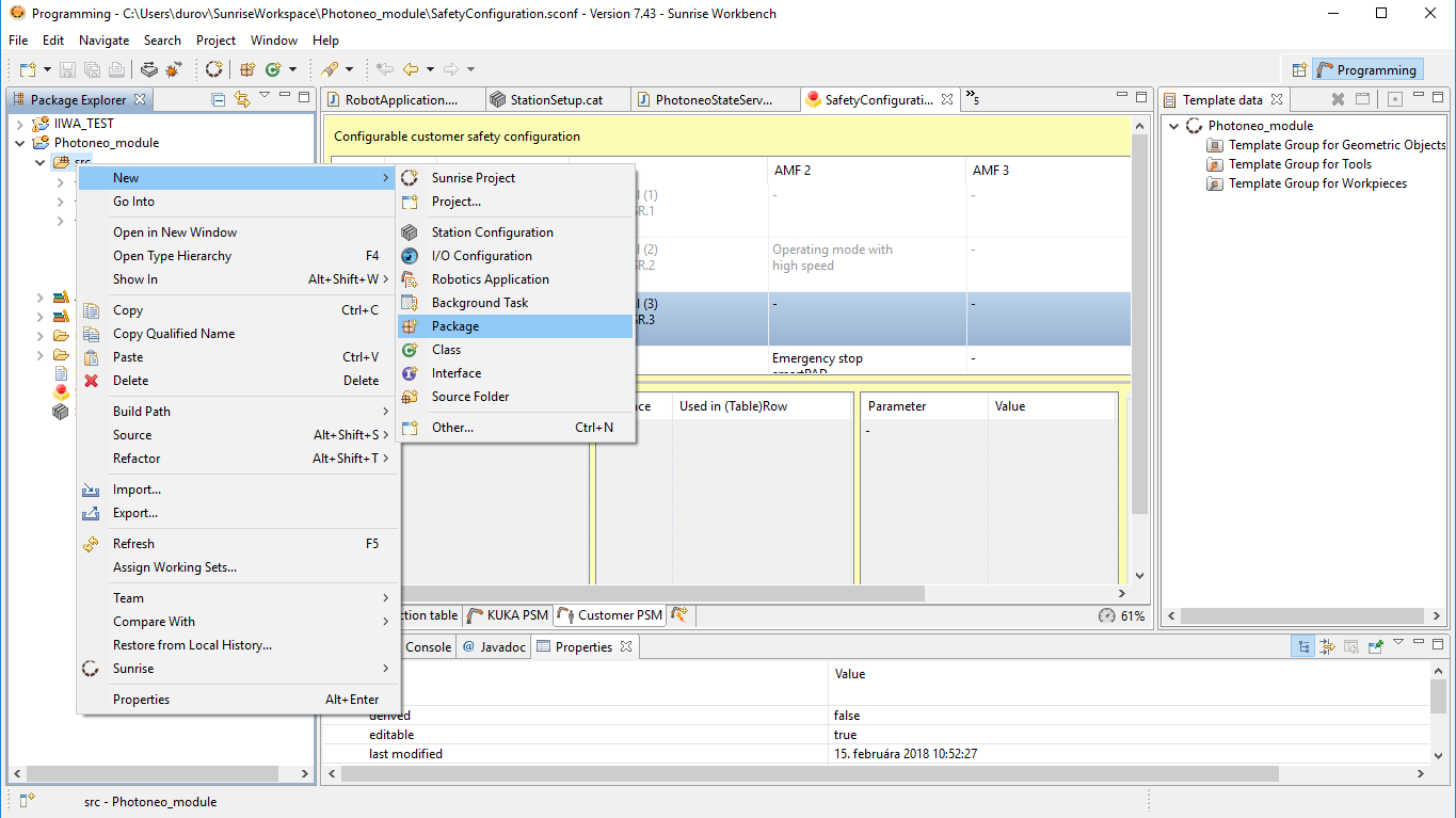
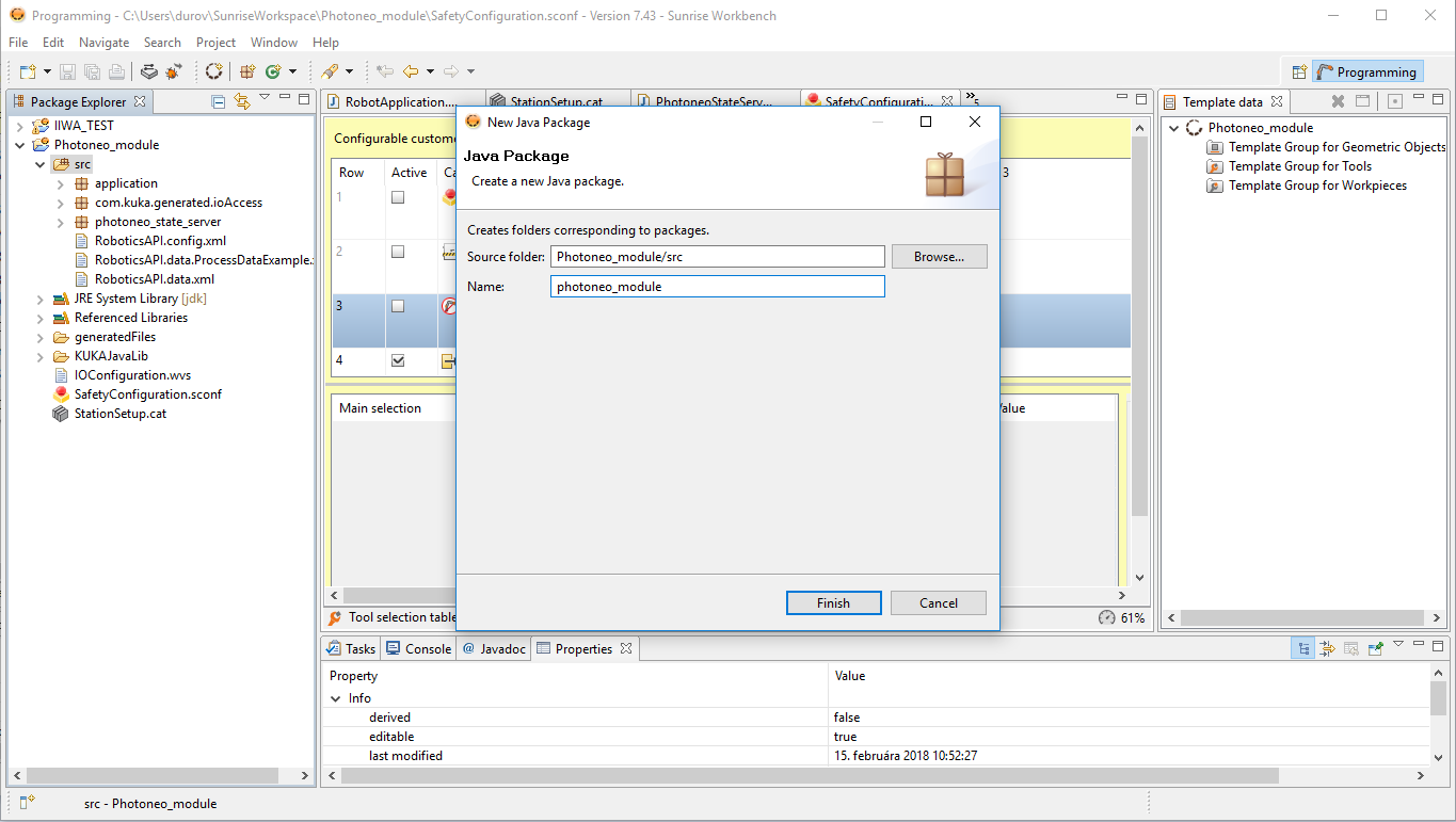
Now create new package. Right Click on src -> New -> Package
Name: photoneo_module
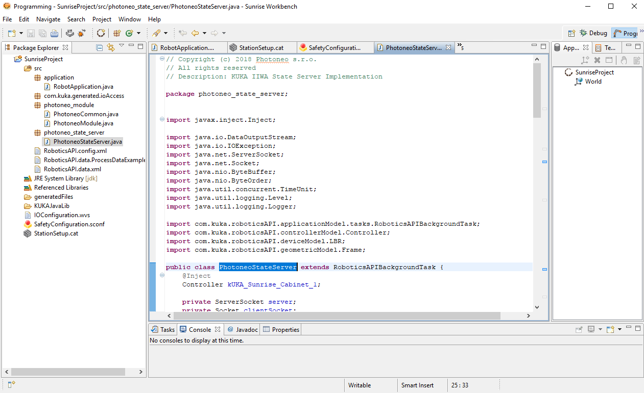
Now copy files from Photoneo KUKA IIWA USB to your project to reach state as shown in the figure below:
In RobotApplication.java edit argument in waitForServer function to meet your Vision Controller network configuration:
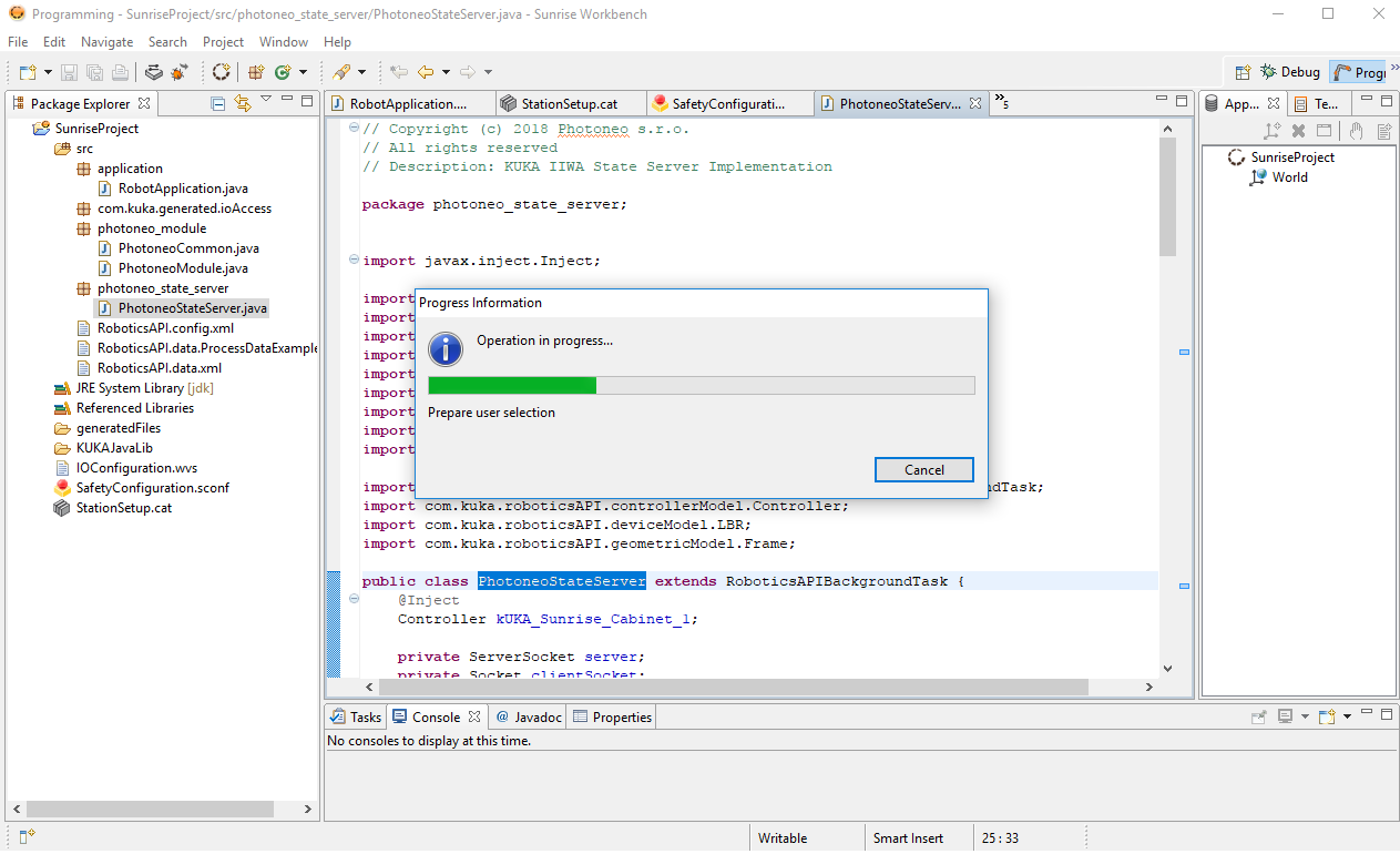
Synchronize project again:
3. Runtime
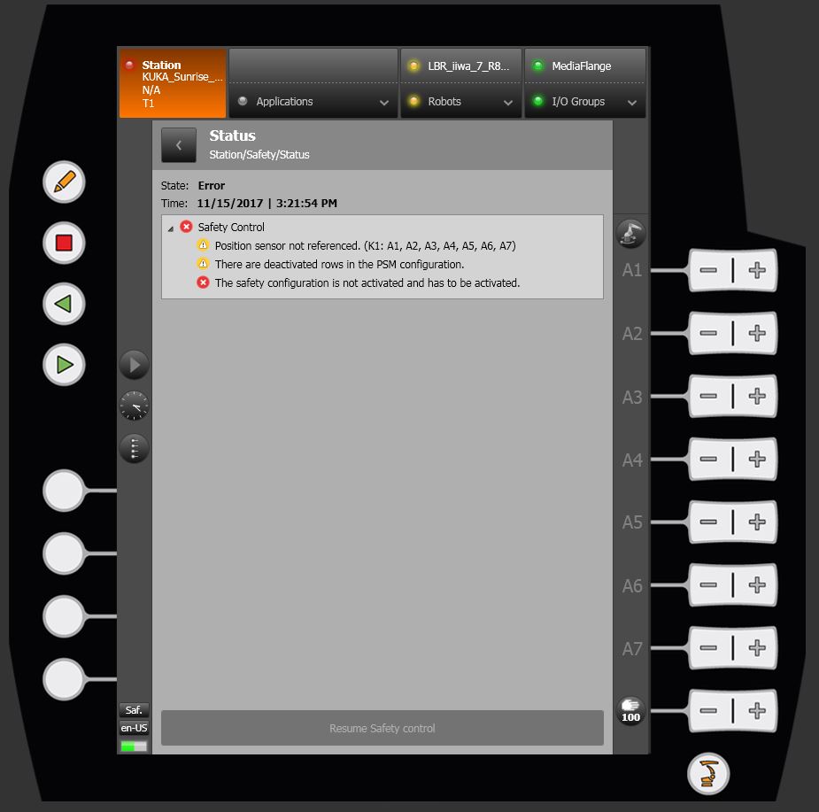
OPTIONAL: If you see these errors after reboot you need to activate safety functions first:
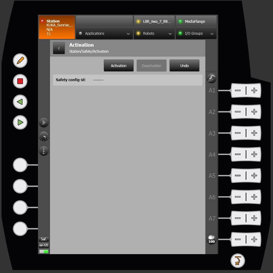
Select Safety->Activate
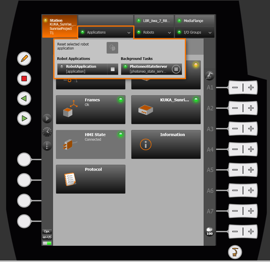
Open Application select box and make sure that you see both PhotoneoStateServer and RobotApplication (Binpicking Client) available. PhotoneoStateServer should be running from boot:
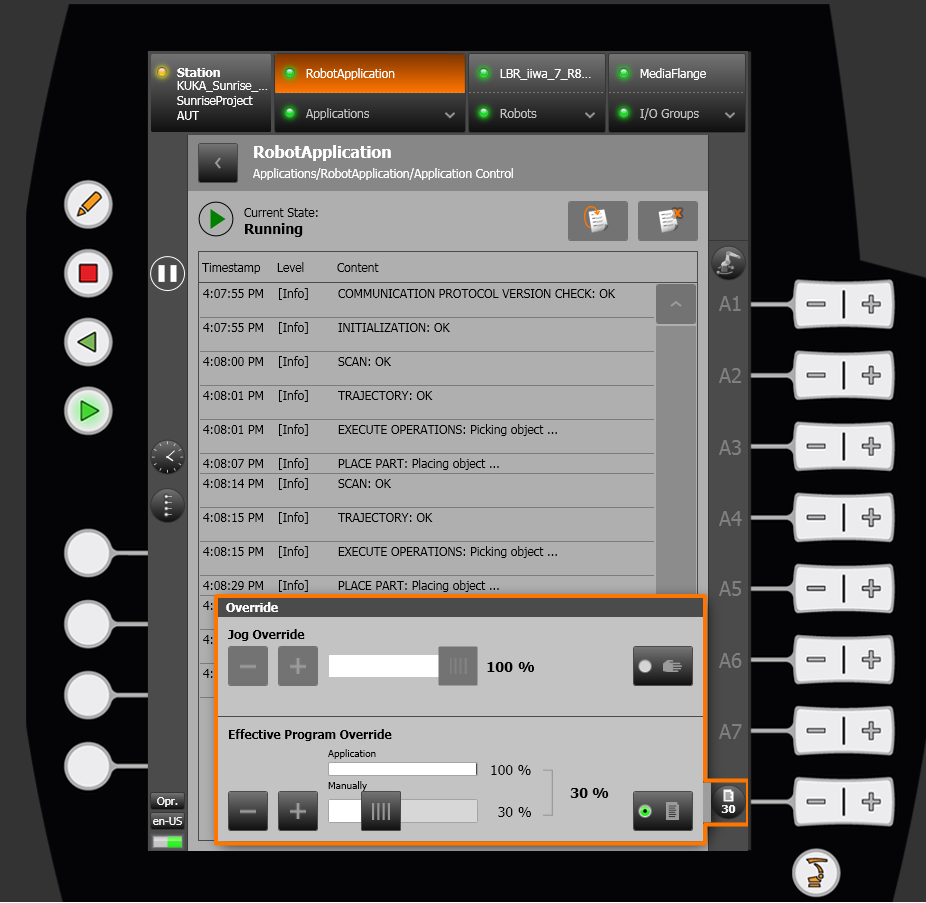
Now you are about to run Client application. Start Vision Controller side first and decrease joint speed to 10% using Effective Program Override option:
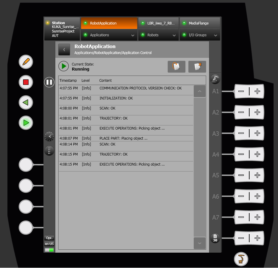
Wait until BinPicking server starts on Vision Side and hit Play button on the pendant to connect robot application to Vision Controller. If everything is okay you should see similar output:
Edit RobotApplication.java to meet your application specific needs and Synchronize project each time you need to update files in robot controller.
